2-14
DCR-PC101/PC101E
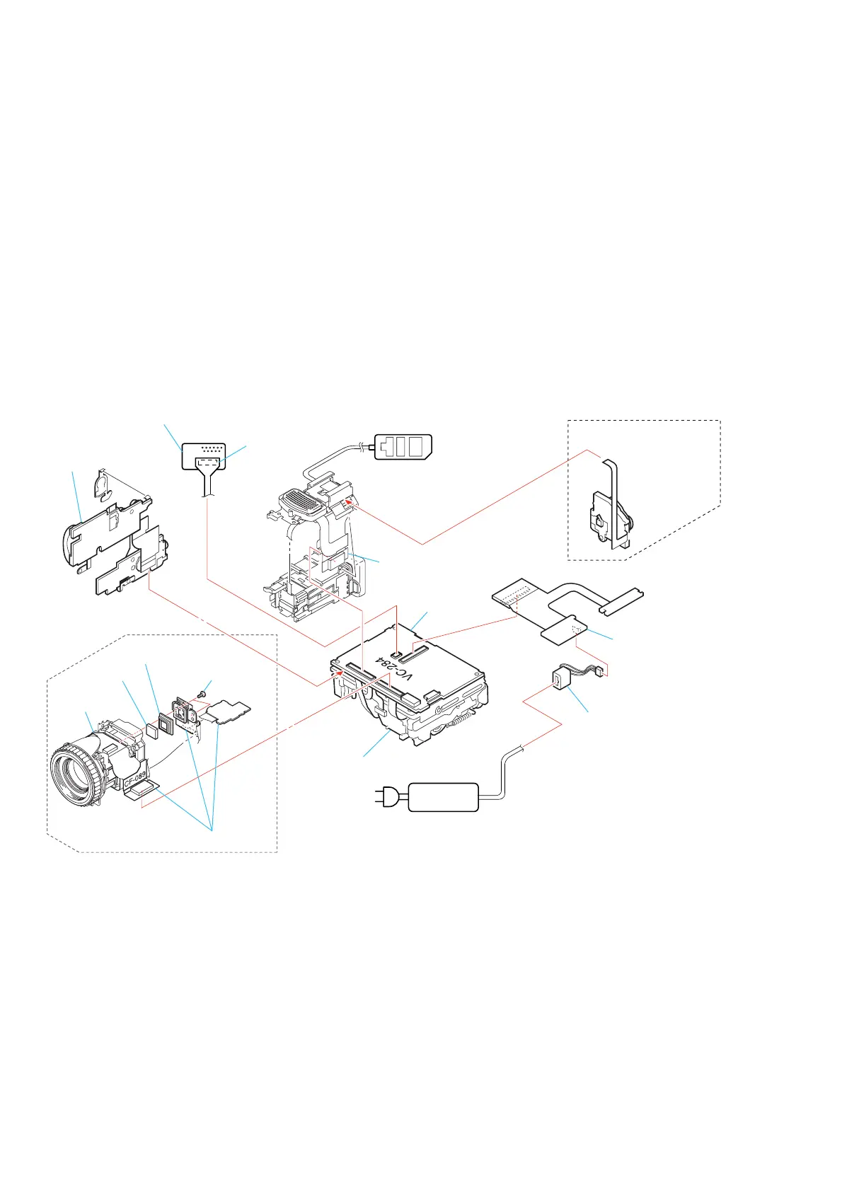
[SERVICE POSITION TO CHECK THE CAMERA SECTION]
Connection to Check the Camera Section
To check the camera section, set the camera to the “Forced camera power ON” mode. (Or, connect the control switch block (PS-2850) to the
CN-402 of ME-020 board and set the power switch to the “CAMERA” position.)
Operate the camera functions of the zoom and focus using the adjustment remote commander (with the HOLD switch set in the OFF
position).
Setting the “Forced Camera Power ON” mode
1) Select page: O, address: 01, and set data: 01.
2) Select page: D, address: 10, set data: 01 and press the PAUSE
button of the adjustment remote commander.
Exiting the “Forced Camera Power ON” mode
1) Select page: O, address: 01, and set data: 01.
2) Select page: D, address: 10, data: 00, and press the PAUSE
button of the adjustment remote commander.
3) Select page : 0, address: 01, and set data: 00.
Two screws
(M1.7
×
5)
CF-089 board
ME-020 board
Lens block
Seal rubber
Optical filter
block
Adjustment remote
commander (RM-95)
AC power
adaptor
AC IN
Control switch block
(PS-2850) (10P)
Control switch block
(FK-2850)
DC-IN connector
BJ-003 board
VC-284 board
Mechanism deck
When exiting the
Forced Camera Power ON mode,
connect the control switch block (PS-2850)
to the CN402 of ME-020 board.
CPC-6 flexible jig
(J-6082-370-B)
CPC-6 terminal board jig
(J-6082-371-A)