DCR-PC101/PC101E
5-23
4. Flange Back Adjustment
RadarWRadarWRadarW
(Using the minipattern box)
The inner focus lens flange back adjustment is carried out auto-
matically. In whichever case, the focus will be deviated during
auto focusing/manual focusing.
Subject Siemens star chart with ND filter
for minipattern box (Note 1)
Measurement Point Adjusting remote commander
Measuring Instrument
Adjustment Page F
Adjustment Address 48 to 58
Specified value Data of page: F, address: 57 is
“00” to “0B”
Note 1: Dark Siemens star chart.
Note 2: Perform “HALL Adjustment” “MR Adjustment” before
this adjustment.
Note 3: Perform the adjustment with the lens in horizontal state.
Note 4: Check that the data of page: 0, address: 10 is “00”.
Note 5: Check that the data of page: 6, address: 02 is “00”.
If not, turn the power of unit OFF/ON.
Switch setting
1) POWER ...................................................................CAMERA
2) NIGHT SHOT.................................................................. OFF
3) COLOR SLOW SHUTTER ............................................ OFF
Preparations before adjustments:
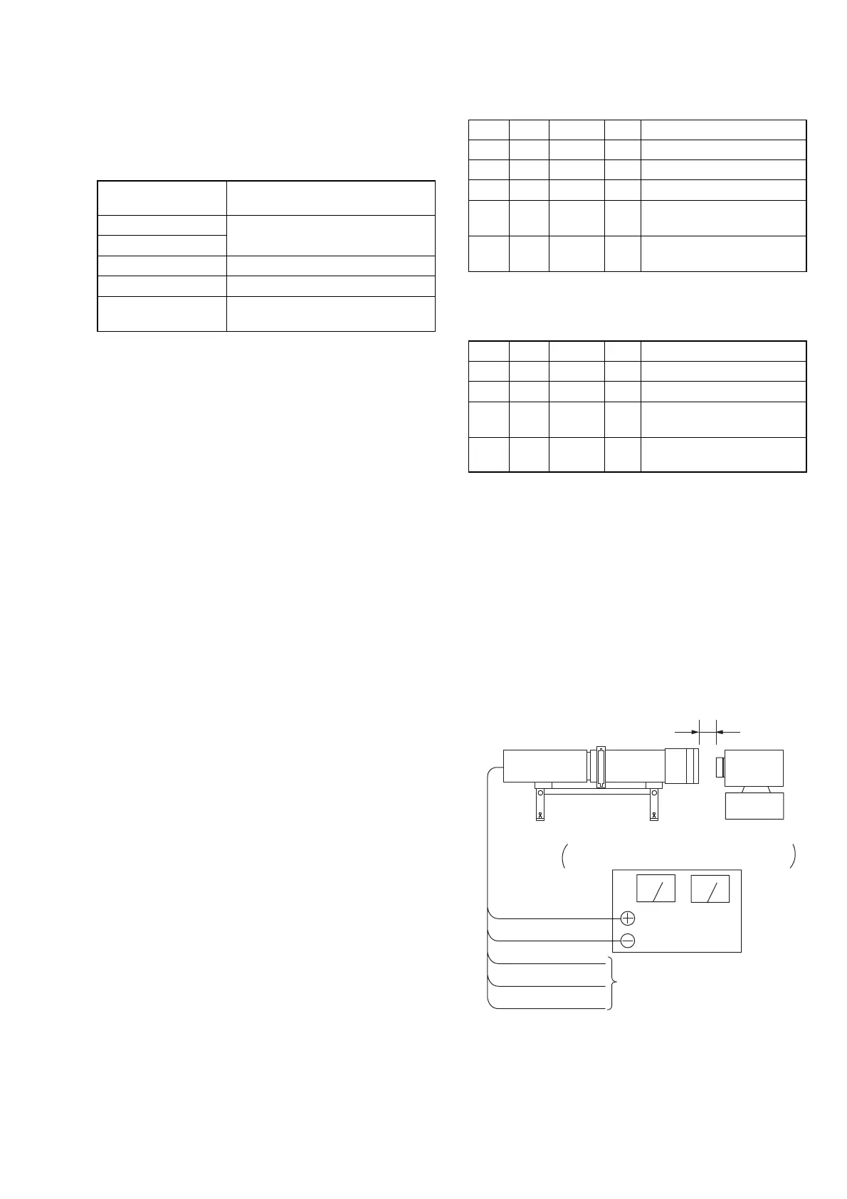
1) The minipattern box is installed as shown in the following fig-
ure.
Note 6: The attachment lenses are not used.
2) Install the minipattern box so that the distance between it and
the front of lens of camcorder is less than 3 cm.
3) Make the height of minipattern box and the camera equal.
4) Check the output voltage of the regulated power supply is the
specified voltage ± 0.01 Vdc.
5) Check that the center of Siemens star chart meets the center of
shot image screen with the zoom lens at TELE end and WIDE
end respectively.
Specified voltage: The specified voltage varies according to the
minipattern box, so adjust the power supply
output voltage to the specified voltage written
on the sheet which is supplied with the
minipattern box.
Minipattern box
Below 3 cm
Camcorder
Camera
table
Red (+)
Black (–)
Yellow (SENS +)
White (SENS –)
Black (GND)
Need not connected
Regulated power supply
Output voltage : Specified voltage ±0.01 Vdc
Output current : more than 3.5 A
Fig.5-1-8
Adjusting method:
Order Page Address Data Procedure
1 0 01 01
2 6 01 13 Press PAUSE button.
3 6 01 27 Press PAUSE button. (Note 7)
46 02
Check the data changes to
“01”.
5F 57
Check the data is “00” to
“0B”.
Note 7: The adjustment data will be automatically input to page:
F, address: 48 to 58.
Processing after Completing Adjustment:
Order Page Address Data Procedure
1 6 01 00 Press PAUSE button.
2 0 01 00
3
Turn OFF the main power
supply.
4
Perform “Flange Back
Check”.