DCR-PC101/PC101E
5-5
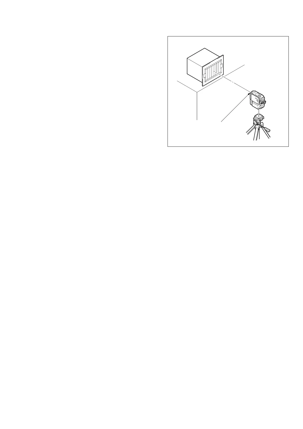
Fig. 5-1-2
1-1-2. Preparations
Note 1: For details of how remove the cabinet and boards, refer
to “2. DISASSEMBLY”.
Note 2: When performing only the adjustments, the lens block
and boards need not be disassembled.
Note 3: Before perform the adjustment, check that the data of
page: 0, address: 10 is “00”.
If not, select page: 0, address: 10, and set data “00”.
1) Connect the equipment for adjustments according to
Fig. 5-1-3.
Note 4: As removing the NS-014 baord (removing the CF-089
board CN104) means removing the lithium 3V power
supply (BT001), data such as date, time, user-set menus
will be lost. After completing adjustments, reset these
data. If the NS-014 board has been removed, the self-
diagnosis data, data on history of use (total drum rota-
tion time, etc. ) will not be lost. (Refer to “SELF-DIAG-
NOSIS FUNCTION” for the self-diagnosis data, and to
“5-4. Service Mode” for the data on the history use)
Note 5: Setting the “Forced Camera Power ON” Mode
1) Select page: 0, address: 01, and set data: 01.
2) Select page: D, address: 10, set data: 01, and press
the PAUSE button of the adjustment remote com-
mander.
The above procedure will enable the camera power
to be turned on with the power switch (PS-2850 block)
removed. After completing adjustments, be sure to
exit the “Forced Camera Power ON Mode”.
Note 6: Exiting the “Forced Camera Power ON” Mode
1) Select page: 0, address: 01, and set data: 01.
2) Select page: D, address: 10, set data: 00, and press
the PAUSE button of the adjustment remote com-
mander.
3) Select page: 0, address: 01, and set data: 00.
Front of the lens
1.5 m
Pattern box