DCR-PC101/PC101E
5-21
1-3. CAMERA SYSTEM ADJUSTMENTS
Before perform the camera system adjustments, check that the
specified values of “VIDEO SYSTEM ADJUSTMENTS” are sat-
isfied. (Except “66MHz/54MHz Origin Oscillation Adjustment”)
Check that the data of page: 0, address: 10 is “00”.
If not, select page: 0, address: 10, and set the data “00”.
1. 66MHz/54MHz Origin Oscillation Adjustment
Set the frequency of the clock for synchronization.
If deviated, the synchronization will be disrupted and the color
will become inconsistent.
Subject Not required
Measurement Point Pin wf of IC1501
Measuring Instrument Frequency counter
Adjustment Page F
Adjustment Address 10
Specified value f = 33000000 ± 165 Hz (NTSC)
f = 27000000 ± 135 Hz (PAL)
Note 1: Check that the data of page: 0, address: 10 is “00”.
Note 2: NTSC model: DCR-PC101
PAL model: DCR-PC101E
Adjusting method:
Order Page Address Data Procedure
1 0 01 01
2F 10
Change the data and set the
frequency (f) to the specified
value.
3 F 10 Press PAUSE button.
4 0 01 00
2. HALL Adjustment
RadarW
RadarW
RadarW
For detecting the position of lens iris and ND filter, adjust the hall
AMP gain and offset.
Subject Not required
Measurement Point Displayed data of page: 1 (Note 1)
Measuring Instrument Adjusting remote commander
Adjustment Page F
Adjustment Address 13 to 18
Specified value 1 D4 to DC
Specified value 2 24 to 2C
Specified value 3 D2 to DE
Specified value 4 22 to 2E
Note 1: The right four digits of the page: 1 displayed data of the
adjusting remote commander.
1 :
XX : XX
IRIS displayed data
ND displayed data
Note 2: Check that the data of page: 0, address: 10 is “00”.
Switch setting
1) POWER .................................................................. CAMERA
Adjusting method:
Order Page Address Data Procedure
1 0 01 01
2 6 01 6D Press PAUSE button. (Note 3)
3 6 02 Check the data changes to “01”.
4 6 01 00 Press PAUSE button.
Note 3: The adjustment data will be automatically input to page:
F, address: 13 to 18.
Checking method:
Order Page Address Data Procedure
1 0 03 03
2 6 01 03 Press PAUSE button.
31
Check that the IRIS dis-
played data (Note 1) satisfied
the specified value 1.
4 6 01 01 Press PAUSE button.
51
Check that the IRIS dis-
played data (Note 1) satisfied
the specified value 2.
6 6 01 69 Press PAUSE button.
71
Check that the ND displayed
data (Note 1) satisfied the
specified value 3.
8 6 01 6B Press PAUSE button.
91
Check that the ND displayed
data (Note 1) satisfied the
specified value 4.
Processing after Completing Adjustment:
Order Page Address Data Procedure
1 6 01 00 Press PAUSE button.
2 0 03 00
3 0 01 00
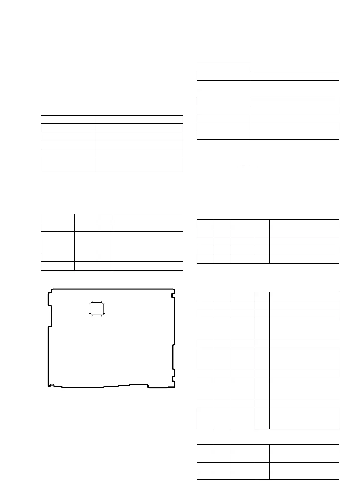
Fig. 5-1-7
112
3625
13
24
48
37
VC-284 board