DCR-PC101/PC101EDCR-PC101/PC101E
COVER
COVER
4-2. SCHEMATIC DIAGRAMS 4-3. PRINTED WIRING BOARDS
4-2. SCHEMATIC DIAGRAMS 4-3. PRINTED WIRING BOARDS
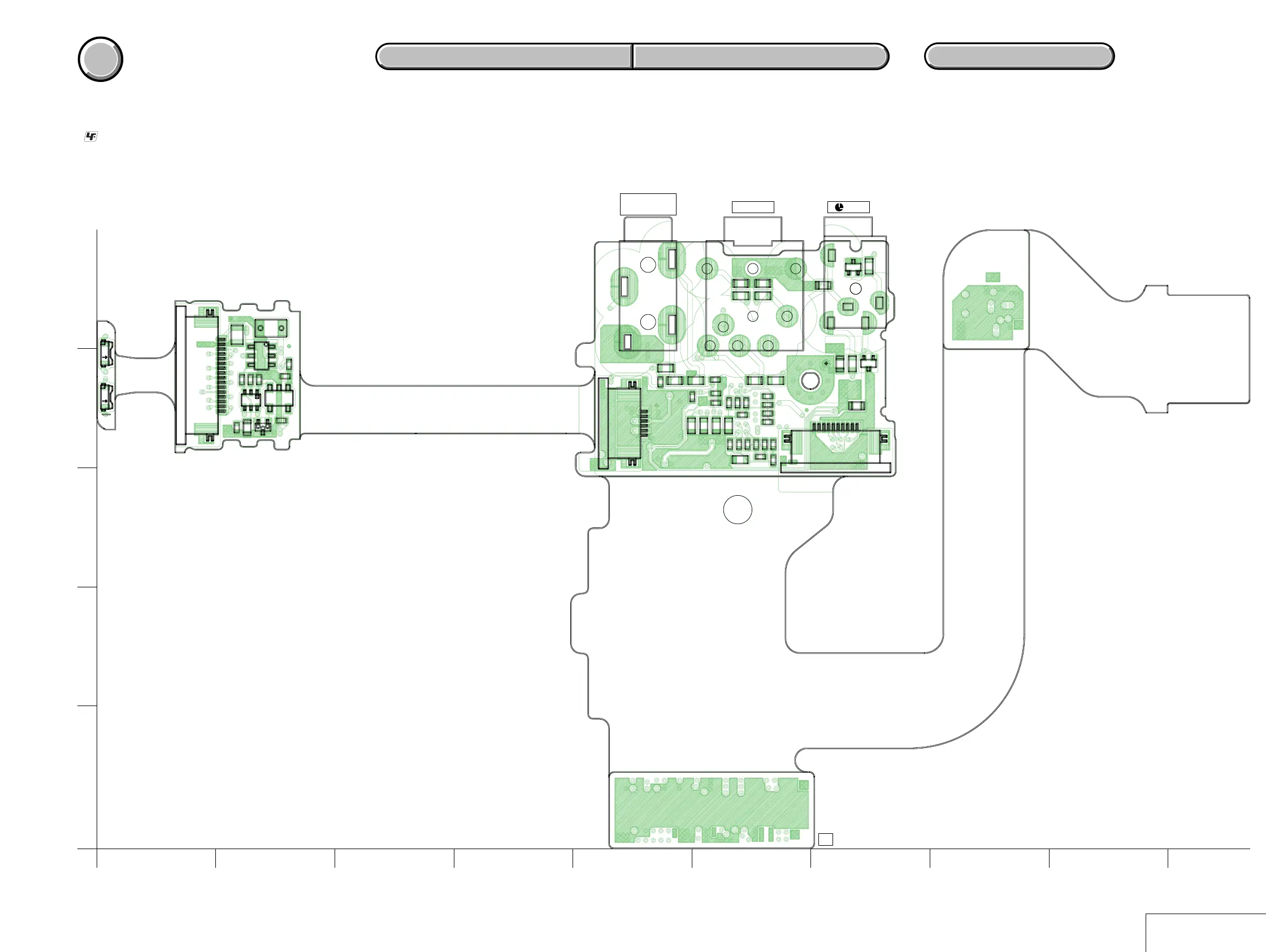
MOUNTED PARTS LOCATION
MOUNTED PARTS LOCATION
4-86
ME-020 (SIDE A)
4-85
ME-020 (MIC AMP, EVF, EVF BACK LIGHT, JACK)
For Printed Wiring Board.
• :Uses unleaded solder.
• ME-020 board is six-layer print board. However, the patterns of
layers 2 to 5 have not been included in the diagram.
• There are a few cases that the part isn't mounted in this model
is printed on this diagram.
• See page 4-106 for printed parts location.
R4405
R4408
R4412
R4413
R4414
R4415
R4416
R4417
R4418
R4419
R4420
R4421
R501
R502
R505
R506
R508
R509
R401
R402
FB408
R411
A
+
C501
E
C
B
Q502
Q501
LND401
D401
D402
123
45
IC501
CN401
16
CN402
110
116
CN502
Q503
AK
D501
AK
D502
C4401
C4412
C4415
C4425
C4426
C4427
C4428
C4429
C4430
C502
C4407
C4408
C4409
C4422
C4424
FB401
FB402
FB403
FB404
FB405
TH501
VDR401
VDR403
VDR404
VDR405
C503
FB407
12
43
J402
J401
J403
ME-020 BOARD(SIDE A)
B
A
C
D
1
2 3 4 5 6 7 8 910
E
D501, 502
(BACK LIGHT)
MIC
(PLUG IN POWER)
AUDIO/VIDEO LANC
A
KK
KK
A
15
1
1-684-895-
05
11