2-6
DCR-PC101/PC101E
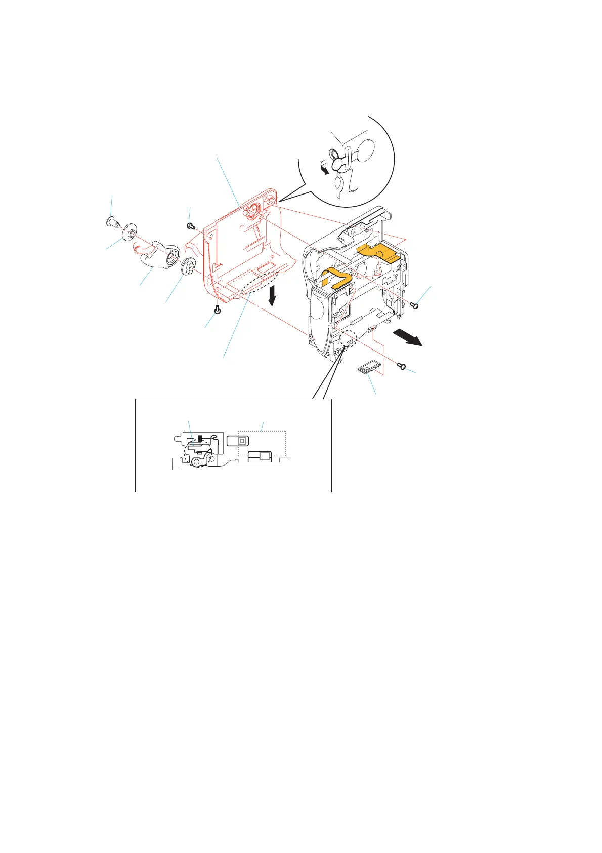
2-8. CABINET (G) ASSEMBLY
5 Two screws
(M1.7)
6 Screw
(M1.7)
qd Cabinet (G) assembly
9 Open the jack cover
1 Special screw
(M2.6)
2 Sleeve
(front)
4 Sleeve
(rear)
3 Hold grip assembly
When install the eject knob,
charge lever is made into the position of a figure.
Note: Make sure to perform checking of operations
after the installation.
Charge lever
Eject knob
0 Pull the bottom part of cabinet (G) assembly
in the direction of arrow, and then remove the claw.
qs Eject knob
8 Two screws
(M1.7 × 4)
7 Four screws
(M1.7 × 4)
qa