DCR-PC101/PC101E
5-24
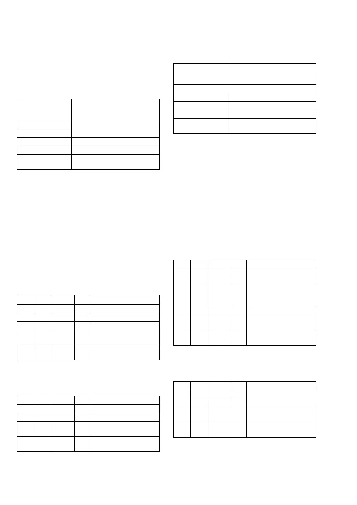
5-2. Flange Back Adjustment (2)
RadarW
RadarW
RadarW
Perform this adjustment after performing “Flange Back Adjust-
ment (1)”.
Subject Subject more than 500 m away
(Subject with clear contrast such as
buildings, etc.)
Measurement Point Adjusting remote commander
Measuring Instrument
Adjustment Page F
Adjustment Address 48 to 58
Specified value Data of page: F, address: 57 is
“00” to “0B”
Note 1: Perform the adjustment with the lens in horizontal state.
Note 2: Check that the data of page: 0, address: 10 is “00”.
Note 3: Check that the data of page: 6, address: 02 is “00”.
If not, turn the power of unit OFF/ON.
Switch setting
1) POWER ...................................................................CAMERA
2) NIGHT SHOT.................................................................. OFF
3) COLOR SLOW SHUTTER ............................................ OFF
Preparations before adjustments:
1) Set the zoom lens to the TELE end and expose a subject that is
more than 500 m away.
(Subjects with clear contrast such as building, etc.)
(Nearby subjects less than 500 m away should not be in the
screen)
Adjusting method:
Order Page Address Data Procedure
1 0 01 01
2 6 01 13 Press PAUSE button.
3
Place ND filter on the lens so
that the optimum image is
obtain.
4 6 01 29 Press PAUSE button. (Note 4)
56 02
Check the data changes to
“01”.
6F 57
Check the data is “00” to
“0B”.
Note 4: The adjustment data will be automatically input to page:
F, address: 48 to 58.
Processing after Completing Adjustment:
Order Page Address Data Procedure
1 6 01 00 Press PAUSE button.
2 0 01 00
3
Turn OFF the main power
supply.
4
Perform “Flange Back
Check”.
5. Flange Back Adjustment
(Using the flange back adjustment chart and
Subject More than 500 m Away)
The inner focus lens flange back adjustment is carried out auto-
matically. In whichever case, the focus will be deviated during
auto focusing/manual focusing.
5-1. Flange Back Adjustment (1)
RadarW
RadarW
RadarW
Subject Flange back adjustment chart
(2.0 m from the front of lens)
(Luminance: 300 to 400 lux)
Measurement Point Adjusting remote commander
Measuring Instrument
Adjustment Page F
Adjustment Address 48 to 58
Specified value Data of page: F, address: 57 is
“00” to “0B”
Note 1: Perform “HALL Adjustment” and “MR Adjustment” be-
fore this adjustment.
Note 2: Perform the adjustment with the lens in horizontal state.
Note 3: Check that the data of page: 0, address: 10 is “00”.
Note 4: Check that the data of page: 6, address: 02 is “00”.
If not, turn the power of unit OFF/ON.
Switch setting
1) POWER...................................................................CAMERA
2) NIGHT SHOT.................................................................. OFF
3) COLOR SLOW SHUTTER ............................................ OFF
Preparations before adjustments:
1) Check that the center of Flange back adjustment chart meets
the center of shot image screen with the zoom lens at TELE
end and WIDE end respectively.
Adjusting method:
Order Page Address Data Procedure
1 0 01 01
2 6 01 13 Press PAUSE button.
3 6 01 15 Press PAUSE button. (Note 5)
46 02
Check the data changes to
“01”.
5F 57
Check the data is “00” to
“0B”.
Note 5: The adjustment data will be automatically input to page:
F, address: 48 to 58.
Processing after Completing Adjustment:
Order Page Address Data Procedure
1 6 01 00 Press PAUSE button.
2 0 01 00
3
Turn OFF the main power
supply.
4
Perform “Flange Back
Adjustment (2)”.