DCR-PC101/PC101E
5-31
14. Auto White Balance Check
RadarW
RadarW
RadarW
Subject Clear chart
(Color reproduction adjustment
frame)
Filter Filter C14 for color temperature
correction
ND filter 1.0, 0.4 and 0.1
Measurement Point Video terminal of Displayed data of
A/V jack page: 1 (Note 2)
(75 Ω terminated)
Measuring Instrument Vectorscope Adjusting remote
commander
Specified Value Fig. 5-1-13 8000 to 8BC0
(A) and (B)
Note 1: Perform “Auto White Balance Adjustment” before this
adjustment.
Note 2: The right four digits of the page: 1 displayed data of the
adjusting remote commander.
1 :
XX : XX
Displayed data
Note 3: Check that the data of page: 0, address: 10 is “00”.
Switch setting
1) POWER ...................................................................CAMERA
2) NIGHT SHOT.................................................................. OFF
3) DIGITAL ZOOM (Menu setting).................................... OFF
4) STEADY SHOT (Menu setting) ..................................... OFF
Checking method:
Order Page Address Data Procedure
1
Check that the lens is not
covered with either filter.
INDOOR luminance point check
2 6 01 0F Press PAUSE button.
3
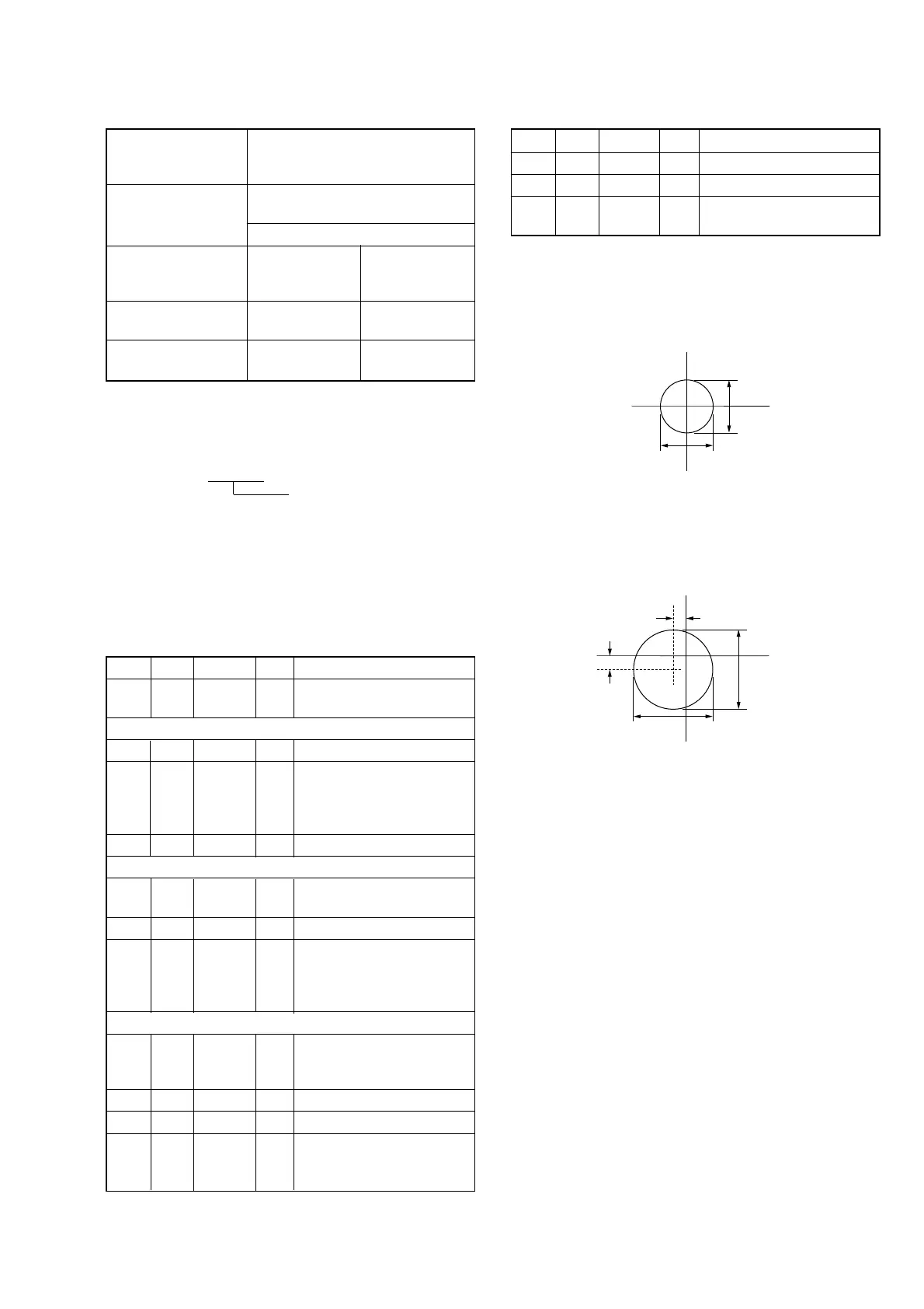
Check that the center of the
white luminance point within
the circle shown Fig 5-1-13.
(A)
4 6 01 00 Press PAUSE button.
OUTDOOR luminance point check
5
Place the C14 filter on the
lens.
6 6 01 3F Press PAUSE button.
7
Check that the center of the
white luminance point within
the circle shown Fig 5-1-13.
(B)
Data check
8
Remove the C14 filter, and
place the ND filter 1.5 (1.0 +
0.4 + 0.1) on the lens.
9 6 01 00 Press PAUSE button.
10 0 03 06
11 1
Check that the displayed data
(Note 2) satisfied the
specified value.
Processing after Completing Adjustment:
Order Page Address Data Procedure
1 6 01 00 Press PAUSE button.
2 0 03 00
3
Remove the ND filter 1.5
(1.0 + 0.4 + 0.1) on the lens.
R-Y
B-Y
2mm
2mm
R-Y
B-Y
1mm
1mm
3mm
3mm
Fig. 5-1-13 (A)
Fig. 5-1-13 (B)