DCR-PC101/PC101E
5-46
3-1-5. Alignment Tapes
Use the alignment tapes shown in the following table.
Use tapes specified in the signal column of each adjustment.
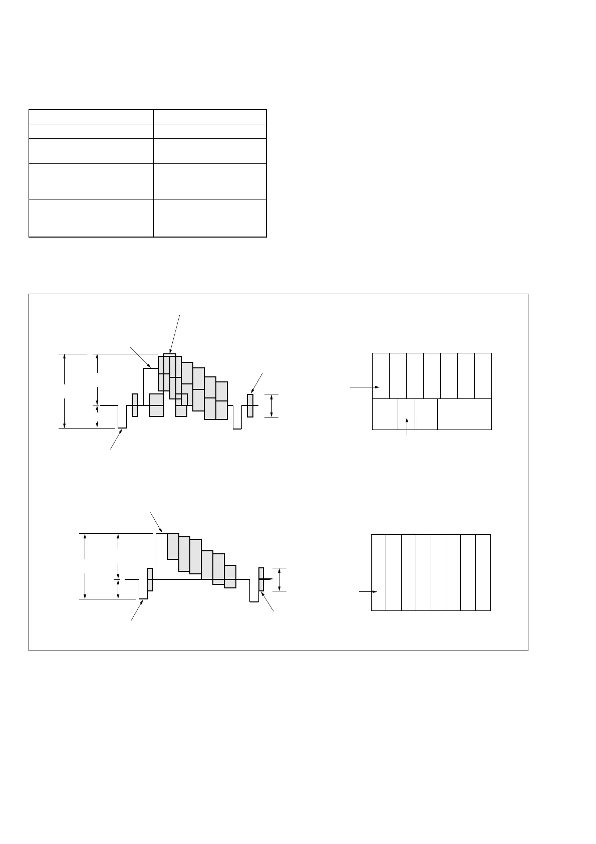
Fig. 5-3-3 shows the 75% color bar signals recorded on the align-
ment tape for Audio Operation Check.
Note: Measure with video terminal (Terminated at 75 Ω)
Name
Tracking standard (XH2-1)
SW/OL standard (XH2-3)
Audio operation check
(XH5-3 (NTSC), XH5-3P
(PAL))
System operation check
(XH5-5 (NTSC), XH5-5P
(PAL))
Use
Tape path adjustment
Switching position adjust-
ment
Audio system adjustment|
Operation check
For NTSC model
For PAL model
Color bar signal waveform Color bar pattern
Color bar signal waveform Color bar pattern
1V
0.714V
0.286V
White (75%)
White (100%)
Yellow
Cyan
Green
Magenta
Red
Blue
Burst signal
0.286V
Q
I
Horizontal sync signal
(75%)
White
Yellow
Cyan
Green
Magenta
Red
Blue
Q
I
White
(100%)
Black
1V
0.7V
0.3V
White (100%)
Yellow
Cyan
Green
Magenta
Red
Blue
Burst signal
Horizontal sync signal
0.3V
(100%)
Yellow
Cyan
Green
Magenta
Red
Blue
White
Black
Fig. 5-3-3. Color bar signal of alignment tapes
3-1-6. Input/Output Level and Impedance
S video input/output
4-pin mini DIN
Luminance signal: 1 Vp-p,
75 Ω (ohms), unbalanced, sync
negative
Chrominance signal:
DCR-PC101: 0.286 Vp-p
DCR-PC101E: 0.3 Vp-p
75 Ω (ohms), unbalanced
A/V (Audio/Video) input/output
AV MINI JACK, input/output
auto switch
Video signal: 1 Vp-p, 75 Ω (ohms),
unbalanced, sync negative
Audio signal: 327 mV, (at output
impedance more than 47 kΩ
(kilohms) )
Input impedance with more than
47 kΩ (kilohms)
Output impedance with less than
2.2 kΩ (kilohms)