2-13
DCR-PC101/PC101E
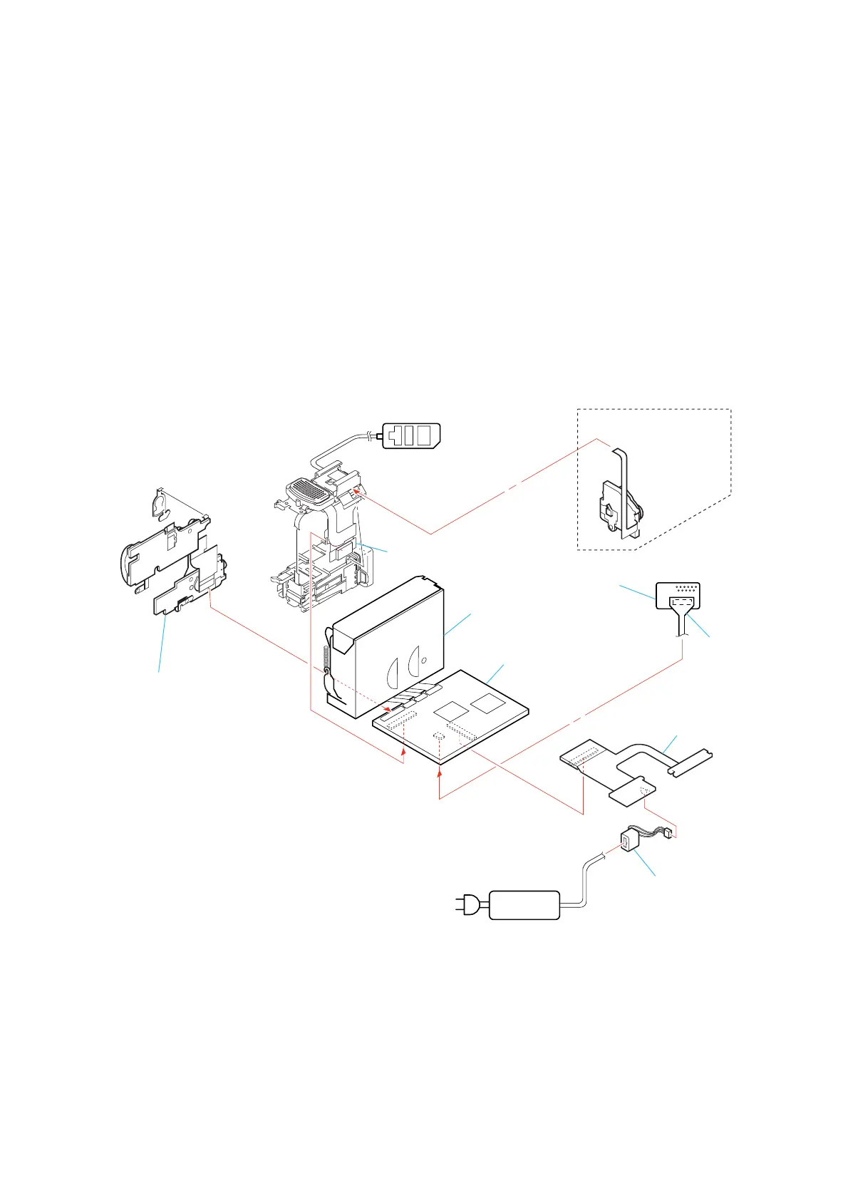
[SERVICE POSITION TO CHECK THE VTR SECTION]
Connection to Check the VTR Section
To check the VTR section, set the VTR to the “Forced VTR power ON” mode. (Or, connect the control switch block (PS-2850) to the CN402
of ME-020 board and set the power switch to the “VIDEO” position.)
Operate the VTR function using the adjustment remote commander (with the HOLD switch set in the OFF position).
ME-020 board
Adjustment remote
commander (RM-95)
AC power
adaptor
AC IN
Control switch block
(PS-2850) (10P)
Control switch block
(FK-2850)
DC-IN connector
BJ-003 board
VC-284 board
Mechanism deck
CPC-6 flexible jig
(J-6082-370-B)
CPC-6 terminal board jig
(J-6082-371-A)
When exiting the Forced VTR Power ON mode, connect the control
switch block (PS-2850) to the CN402 of ME-020 board. Or,
when ejecting the cassette, connect the control switch block (PS-1770)
to the CN402 of ME-020 board. and press the EJECT switch.
Setting the “Forced VTR Power ON” mode
1) Select page: 0, address: 01, and set data: 01.
2) Select page: D, address: 10, set data: 02 and press the PAUSE
button of the adjustment remote commander.
Exiting the “Forced VTR Power ON” mode
1) Select page: 0, address: 01, and set data: 01.
2) Select page: D, address: 10, data: 00, and press the PAUSE
button of the adjustment remote commander.
3) Select page: 0, address: 01, and set data: 00.