DCR-PC101/PC101E
5-26
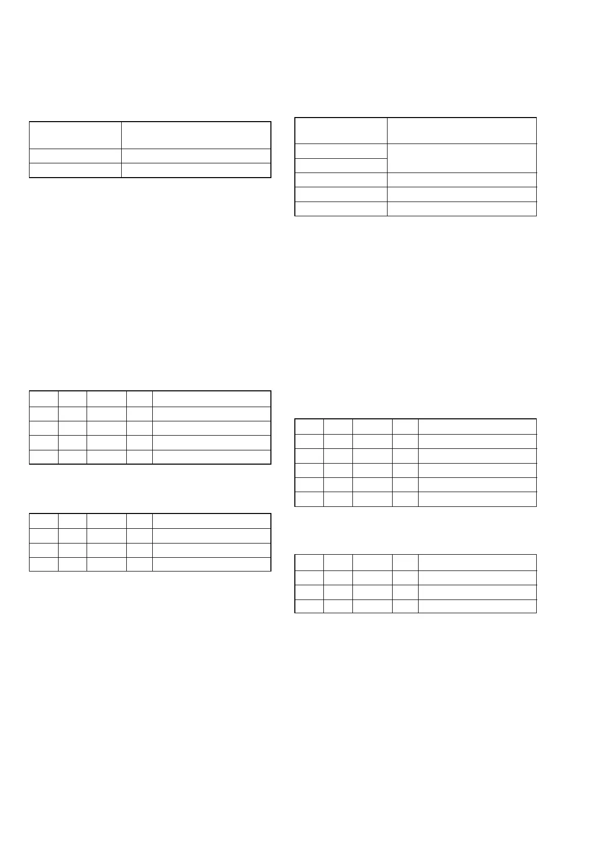
9. Mechanical Shutter Adjustment
RadarWRadarWRadarW
Adjust the close time and loss time every F number of the me-
chanical shutter and the high-speed shutter correction value to
correct the luminous exposure.
Subject Clear chart (All white)
(Zoom lens at WIDE end) (Note 2)
Measurement Point Adjusting remote commander
Measuring Instrument
Adjustment Page F
Adjustment Address 76 to 8B
Specified Value Data of page: 6, address: A8 is “00”
Note 1: Perform “HALL Adjustment”, “Flange Back Adjust-
ment” and “F No. & ND Light Quality Standard Data
Input” before this adjustment.
Note 2: With the ZOOM at WIDE end, set the distance where
the clear chart is shot with all-white signal.
Note 3: Check that the data of page: 0, address: 10 is “00”.
Note 4: Check that the data of page: 6, address: 02 is “00”.
If not, turn the power of unit OFF/ON.
Switch setting
1) POWER ...................................................................CAMERA
2) NIGHT SHOT.................................................................. OFF
3) ZOOM .................................................................... WIDE end
4) DIGITAL ZOOM (Menu setting).................................... OFF
5) STEADY SHOT (Menu setting) ..................................... OFF
Adjusting method:
Order Page Address Data Procedure
1 0 01 01
26 9C01
3 6 01 AD Press PAUSE button. (Note 5)
4 6 02 Check the data changes to “01”.
5 6 A8 Check the data is “00”.
Note 5: The adjustment data will be automatically input to page:
F, address: 76 to 8B.
Processing after Completing Adjustment:
Order Page Address Data Procedure
1 6 01 00 Press PAUSE button.
26 9C00
3 0 01 00
8. F No. & ND Light Quality Standard Data Input
RadarWRadarWRadarW
Correct the lens iris and the dispersion of the ND filter light quan-
tity.
Subject Clear chart (All white)
(Zoom lens at WIDE end) (Note 3)
Adjustment Page F
Adjustment Address 1C to 23
Note 1: Perform “MAX GAIN Adjustment” before this adjust-
ment.
Note 2: Perform “Mechanical Shutter Adjustment” after this ad-
justment.
Note 3: With the ZOOM at WIDE end, set the distance where
the clear chart is shot with all-white signal.
Note 4: Check that the data of page: 0, address: 10 is “00”.
Note 5: Check that the data of page: 6, address: 02 is “00”.
If not, turn the power of unit OFF/ON.
Switch setting
1) POWER...................................................................CAMERA
2) NIGHT SHOT.................................................................. OFF
3) ZOOM .................................................................... WIDE end
4) DIGITAL ZOOM (Menu setting) .................................... OFF
5) STEADY SHOT (Menu setting) ..................................... OFF
Adjusting method:
Order Page Address Data Procedure
1 0 01 01
26 2C01
3 6 01 BB Press PAUSE button. (Note 6)
4 6 02 Check the data changes to “01”.
Note 6: The adjustment data will be automatically input to page:
F, address: 1C to 23.
Processing after Completing Adjustment:
Order Page Address Data Procedure
1 6 01 00 Press PAUSE button.
26 2C00
3 0 01 00