DCR-PC101/PC101E
5-42
5-2. MECHANISM SECTION ADJUSTMENTS
On the mechanism section adjustment
For details of mechanism section adjustments, checks, and replace-
ment of mechanism parts, refer to the separate volume “DV ME-
CHANICAL ADJUSTMENT MANUAL VI J Mechanism ”.
2-1. HOW TO ENTER RECORD MODE WITHOUT
CASSETTE
1) Connect the adjustment remote commander to the LANC jack.
2) Turn the HOLD switch of the adjustment remote commander
to the ON position.
3) Close the cassette compartment without the cassette.
4) Select page: 3, address: 01, set data: 0C, and press the PAUSE
button of the adjustment remote commander.
(The mechanism enters the record mode automatically.)
Note: The function buttons become inoperable.
5) To quit the record mode, select page: 3, address: 01, set data:
00, and press the PAUSE button of the adjustment remote com-
mander. (Whenever you want to quit the record mode, be sure
to quit following this procedure.)
2-2. HOW TO ENTER PLAYBACK MODE WITHOUT
CASSETTE
1) Connect the adjustment remote commander to the LANC jack.
2) Turn the HOLD switch of the adjustment remote commander
to the ON position.
3) Close the cassette compartment without the cassette.
4) Select page: 3, address: 01, set data: 0B, and press the PAUSE
button of the adjustment remote commander.
(The mechanism enters the playback mode automatically.)
Note: The function buttons become inoperable.
5) To quit the playback mode, select page: 3, address: 01, set
data: 00, and press the PAUSE button of the adjustment re-
mote commander. (Whenever you want to quit the playback
mode, be sure to quit following this procedure.)
2-3. TAPE PATH ADJUSTMENT
1. Preparation for Adjustment
1) Clean the tape running side (tape guide, drum, capstan shaft,
pinch roller, etc.).
2) Connect the adjustment remote commander to the LANC jack.
3) Turn the HOLD switch of the adjustment remote commander
to the ON position.
4) Connect an oscilloscope to VC-284 board CN1006 via the
CPC-6 flexible jig (J-6082-370-B) and CPC-6 terminal board
jig (J-6082-371-A).
Channel 1: VC-284 board, CN1006 Pin w; (Note)
External trigger: VC-284 board, CN1006 Pin qj
Note: Connect a 75 Ω resistor between pins w; of CN1006
and ql (GND).
75 Ω resistor (Parts code: 1-247-804-11)
5) Playback the alignment tape for tracking. (XH2-1)
6) Select page: 3, address: 33, and set data: 08.
7) Select page: 3, address: 26, and set data: 31.
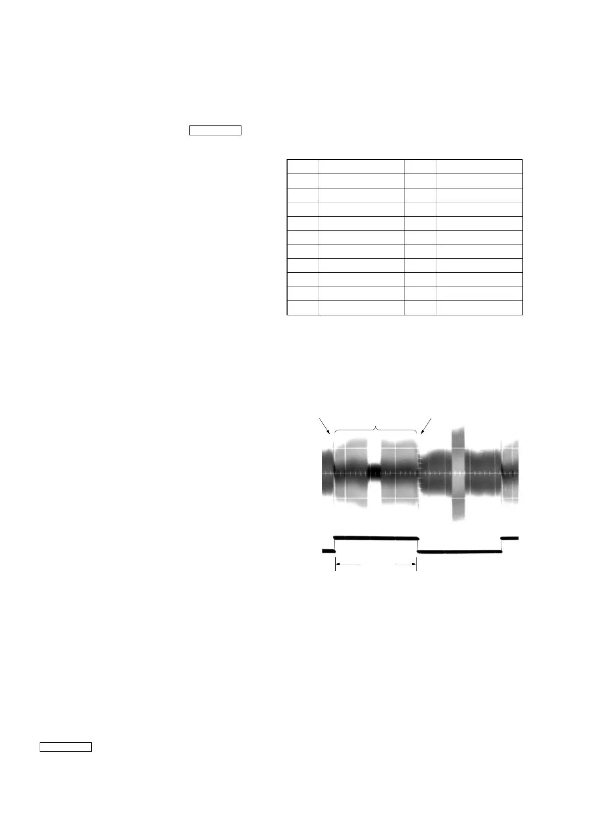
8) Check that the oscilloscope RF waveform is normal at the en-
trance and exit.
If not normal, adjust according to the separate volume
“DV MECHANICAL ADJUSTMENT MANUAL VI
J Mechanism ” .
CN1006 of VC-284 board
2. Procedure after operations
1) Connect the adjustment remote commander to the LANC jack
and set the HOLD switch to the ON position.
2) Select page: 3, address: 26, and set data: 00.
3) Select page: 3, address: 33, and set data: 00.
Pin No.
Signal Name
Pin No.
Signal Name
1 FLASH_UNREG 2 D_2.8V
3 EVF_LED_DA 4 EVF_VG
5 EVF_VCO 6 GND
7 MD2 8 XCS_MC_FLASH
9 XINIT 10 XCS_ST_IMAGE_IC
11 DRUM_ON 12 FRRV
13 REC_CRRT1 14 REC_CRRT0
15 REG_GND 16 HI_XRESET
17 SWP 18 RF_IN
19 GND 20 RF_MON
Fig. 5-2-1
CH1
Entrance side Exit side
Check this section
(Normal waveform)
CH2
(Trigger)
3.3msec