DCR-PC101/PC101E
5-53
5. PLL f
0
& LPF f
0
Final Adjustment (VC-284 board)
RadarW
RadarW
RadarW
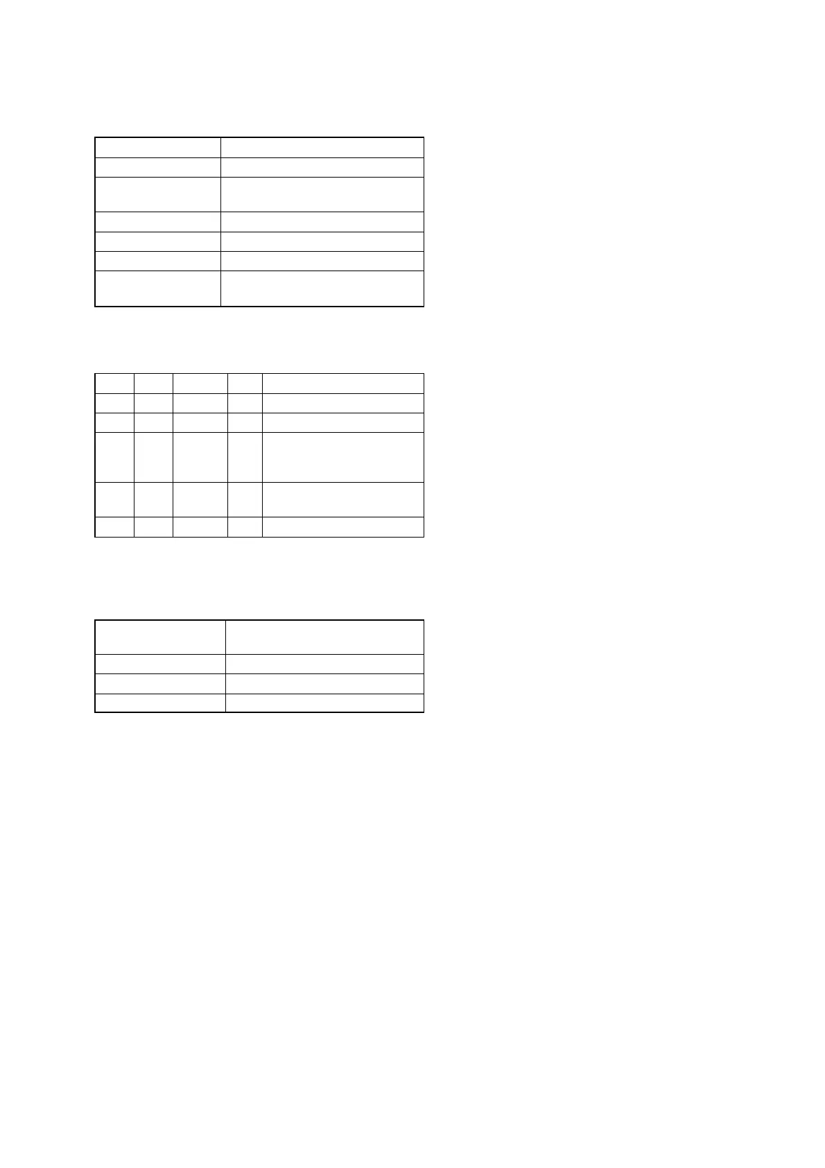
Mode VTR stop
Signal No signal
Measurement Point Displayed data of page: 3, address:
02 and 03
Measuring Instrument Adjusting remote commander
Adjustment Page C
Adjustment Address 1F, 20, 22, 29
Specified value The data of page: 3, address: 02 is “00”
The data of page: 3, address: 03 is “00”
Note 1: Check that the data of page: 0, address: 10 is “00”.
Adjusting method:
Order Page Address Data Procedure
1 0 01 01
2 3 01 30 Press PAUSE button.
33 02
Check the data changes to
“00” within 5 seconds.
(Note 2)
43 03
Check the data is “00”.
(Note 2, 3)
5 0 01 00
Note 2: If check is NG, the machine is defective.
Note 3: If bit value of bit2, bit3, bit4, bit5 or bit6 is “1”, adjust-
ment has errors. For the error contents, see the follow-
ing table. (For the bit values, refer to “5-4. SERVICE
MODE”, “4-3. 3. Bit value discrimination”.)
Bit value of page: 3,
address: 03 data
Error contents
bit2 = 1 or bit 3 =1 PLL f
0
fine adjustment is defective
bit4 = 1 or bit 5 =1 PLL f
0
adjustment is defective
bit6 = 1 LPF f
0
adjustment is defective