DCR-PC101/PC101E
5-35
3. RGB AMP Adjustment (VC-284 board)
Set the D Range of the RGB decoder for driving the LCD to the
specified value.
If deviated, the EVF screen image will be blackish or saturated
(whitish).
Mode CAMERA
Subject Not required
Measurement Point Pin 4 of CN1006 (EVF_VG)
Measuring Instrument Oscilloscope
Adjustment Page C
Adjustment Address 54
Specified Value A = 7.20 ± 0.1 Vp-p
Note: Check that the data of page: 0, address: 10 is “00”.
Adjusting method:
Order Page Address Data Procedure
1 0 01 01
2C 54
Change the data and set the
voltage (A) to the specified
value.
3 C 54 Press PAUSE button.
4 0 01 00
2. Back Light Adjustment (VC-284 board)
Set the back light luminance.
If deviated, the image may become dark or bright.
Mode CAMERA
Subject Not required
Measurement Point Pin 3 of CN1006 (EVF_LED_DA)
Measuring Instrument Digital voltmeter
Adjustment Page C
Adjustment Address 4F, 50
Specified Value A = 2.10 ± 0.05 Vdc
Note 1: Check that the data of page: 0, address: 10 is “00”.
Adjusting method:
Order Page Address Data Procedure
1 0 01 01
2 3 0C 20 Press PAUSE button.
3 3 22 11 Press PAUSE button.
4C 50
Change the data and set the
DC voltage (A) to the
specified value.
5 C 50 Press PAUSE button.
6C 50
Read the data and this data is
named D
50
.
7
Convert D
50
to decimal
notation, and obtain D
50
’.
(Note 2)
8
Calculate D
4F
’ using
following equations.
(decimal calculation)
D
4F
’ = D
50
’– 96
9
Convert D
4F
’ to a hexadeci-
mal number, and obtain D
4F
.
(Note 2)
10 C 4F D
4F
Press PAUSE button.
11 3 0C 00 Press PAUSE button.
12 3 22 00 Press PAUSE button.
13 0 01 00
Note 2: Refer to table 5-4-1. “Hexadecimal-decimal conversion
table”
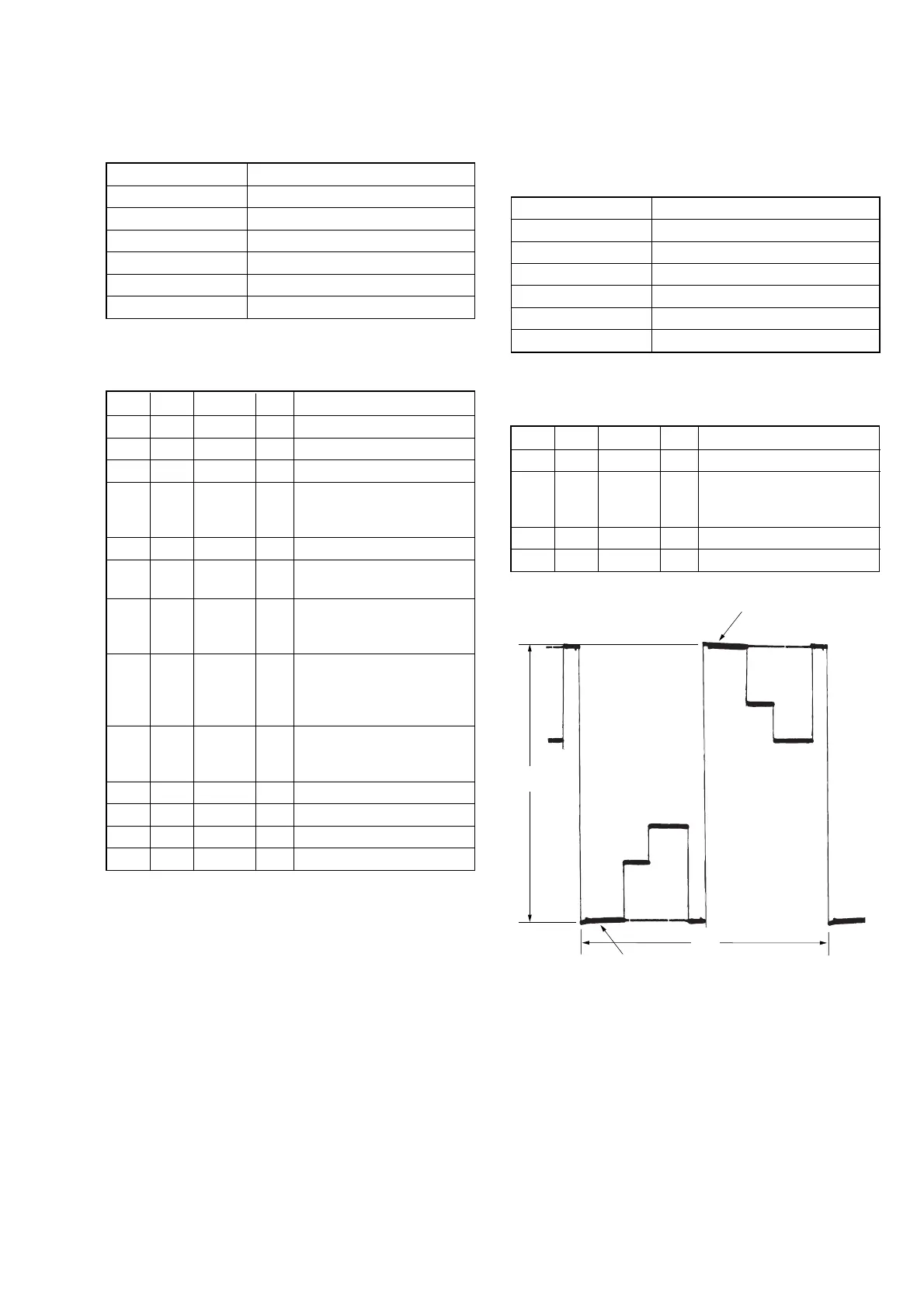
A: Between the reversed waveform pedestal
and non-reversed waveform pedestal
Fig. 5-1-15
Pedestal
Pedestal
A
2H