DCR-PC101/PC101E
5-7
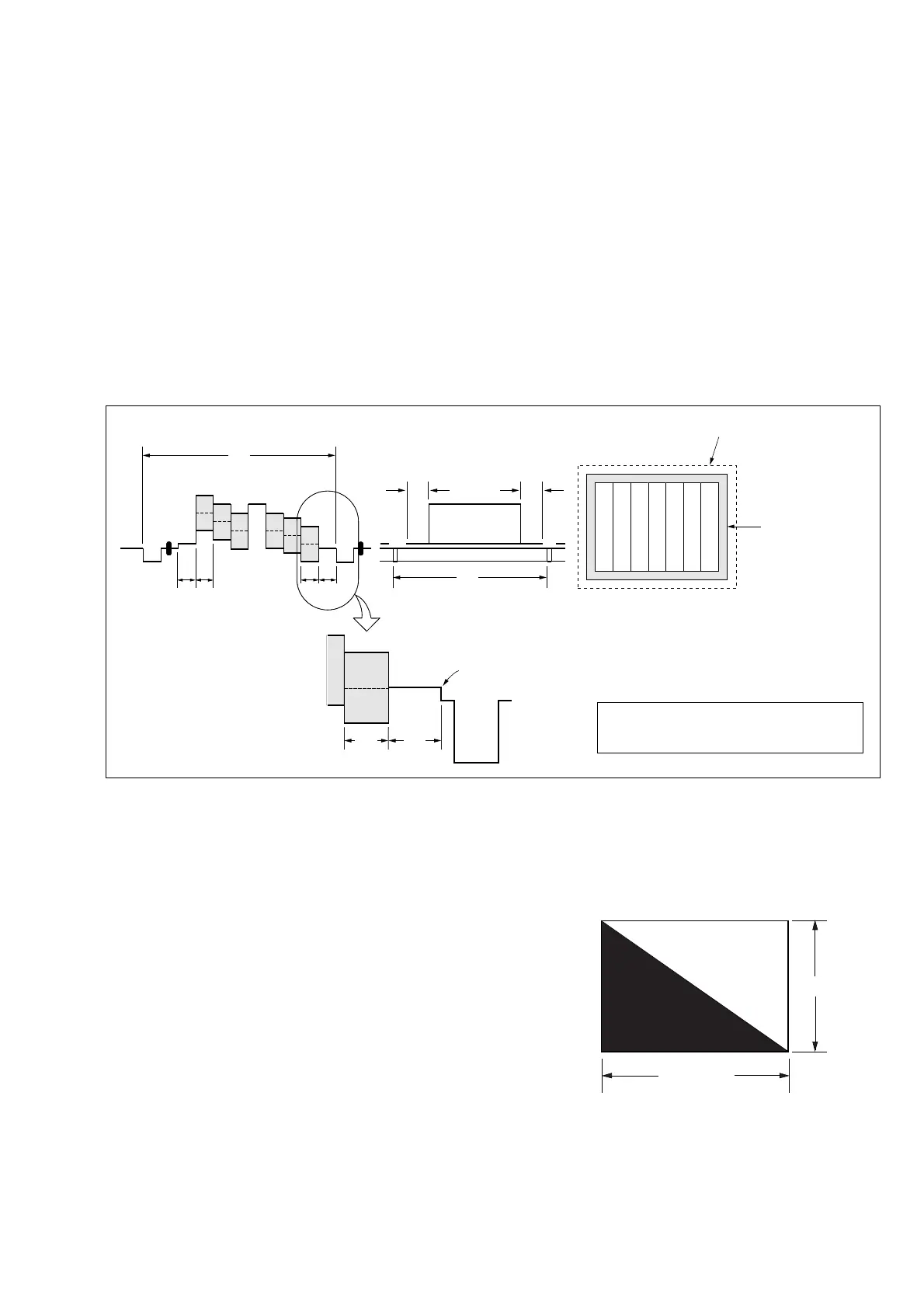
H
A=B
C=D
AB B
CD
A
Enlargement
V
Electronic beam scanning frame
CRT picture frame
B
A
Difference in level
Yellow
Cyan
Green
White
Magenta
Red
Blue
Yellow
Cyan
Green
White
Magenta
Red
Blue
Color bar chart (Color reproduction adjustment frame)
Fig. a
(VIDEO terminal of A/V jack
output waveform)
Fig. b (monitor TV picture)
Adjust the camera zoom and direction to
obtain the output waveform shown in Fig. a and
the monitor TV display shown in Fig. b.
1-1-3. Precaution
1. Setting the Switch
Unless otherwise specified, set the switches as follows and perform adjustments without loading cassette.
1. POWER switch (PS-2850 block) ..........................CAMERA
2. NIGHT SHOT switch (Lens block) ............................... OFF
3. FOCUS switch (FK-2850 block) ......................... MANUAL
4. BACK LIGHT (FK-2850 block) .................................... OFF
5. COLOR SLOW S/SUPPER NS ..................................... OFF
6. FUNCTION settings of the touch panel
• DIGITAL EFFECT ...................................................... OFF
• EXPOSURE .............................................................. AUTO
• PROGRAM AE (MENU setting) ............................. AUTO
• PICTURE EFFECT (MENU setting) .......................... OFF
• WHITE BALANCE (MENU setting)....................... AUTO
• DIGITAL ZOOM (MENU setting) ............................. OFF
• STEADY SHOT (MENUsetting) ................................ OFF
• DEMO MODE (MENU setting).................................. OFF
2. Order of Adjustments
Basically carry out adjustments in the order given.
Fig. 5-1-4
3. Subjects
1) Color bar chart (Color reproduction adjustment frame)
When performing adjustments using the color bar chart, adjust
the picture frame as shown in Fig. 5-1-4. (Color reproduction
adjustment frame)
2) Clear chart (Color reproduction adjustment frame)
Remove the color bar chart from the pattern box and insert a
clear chart in its place. (Do not perform zoom operations during
this time)
3) Chart for flange back adjustment
Join together a piece of white A0 size paper (1189mm × 841
mm) and a piece of black paper to make the chart shown in
Fig. 5-1-5.
Note: Use a non-reflecting and non-glazing vellum paper. The
size must be A0 or larger and the joint between the white
and black paper must not have any undulations.
Fig. 5-1-5
Black
White
841 mm
1189 mm