DCR-PC101/PC101E
5-52
4-2. AGC Center Level Adjustment (VC-284 board)
RadarW
RadarW
RadarW
Mode VTR playback
Subject Recorded signal at “Preparations
before adjustments”
Measurement Point CH1: Pin w; of CN1006 (RF MON)
(Note 1)
CH2 (Trigger): Pin qj of CN1006
(SWP)
Measuring Instrument Oscilloscope
Adjustment Page C
Adjustment Address 1E
Specified value The data of page: 3, address: 03 is “00”
Note 1: Connect a 75 Ω resistor (1-247-804-11) between Pin
w; and Pin ql (GND) of CPC jig.
Adjusting method:
Order Page Address Data Procedure
1
Playback the recorded signal
at“Preparations before
adjustments”.
2 0 01 01
3 3 33 08
4
Confirm that the playback
RF signal is stable.
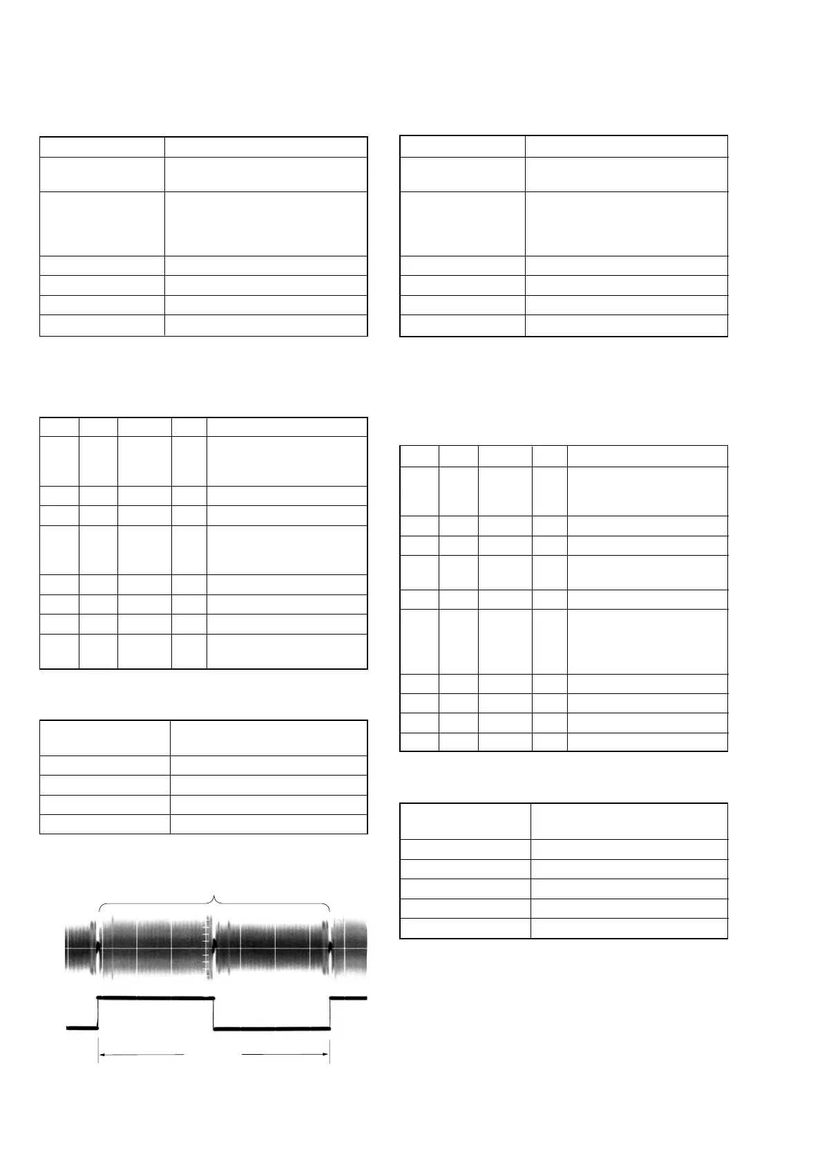
(Fig 5-3-5)
5 3 01 23 Press PAUSE button.
6 3 02 Check the data changes to “00”
7 3 03 Check the data is “00”. (Note 2)
8 0 01 00
Perform “APC & AEQ
Adjustment”.
Note 2: If the data is other than “00”, adjustment has errors. (Take
an appropriate remedial measures according to the er-
rors referring to the following table)
Data of page: 3,
address: 03
Contents of defect
20 Perform re-adjustment. (Note 3)
30 The machine is defective.
40 Perform re-adjustment. (Note 3)
50 The machine is defective.
Note 3: If this data displayed twice successively, the machine is
defective.
Fig. 5-3-5
4-3. APC & AEQ Adjustment (VC-284 board)
RadarW
RadarW
RadarW
Mode VTR playback
Subject Recorded signal at “Preparations
before adjustments”
Measurement Point CH1: Pin w; of CN1006 (RF MON)
(Note 1)
CH2 (Trigger): Pin qj of CN1006
(SWP)
Measuring Instrument Oscilloscope
Adjustment Page C
Adjustment Address 18, 19, 1B, 1C, 21, 2C
Specified value The data of page: 3, address: 03 is “00”
Note 1: Connect a 75 Ω resistor (1-247-804-11) between Pin w;
and Pin ql (GND) of CPC jig.
Note 2: Perform “AGC Center Level Adjustment” before this ad-
justment.
Adjusting method:
Order Page Address Data Procedure
1
Playback the recorded signal
at“Preparations before
adjustments”.
2 0 01 01
3 3 33 08
4
Confirm that the playback RF
signal is stable. (Fig 5-3-5)
5 3 01 07 Press PAUSE button.
63 02
Check the data changes from
“07”to “00” in about 20
seconds after pressing
PAUSE button
7 3 03 Check the data is “00”. (Note 3)
8 7 30 00
9 3 33 00
10 0 01 00
Note 3: If the data is other than “00”, adjustment has errors.
(Take an appropriate remedial measures according to the
errors referring to the following table)
Data of page: 3,
address: 03
Contents of defect
20 Perform re-adjustment. (Note 4)
30 The machine is defective.
50 Perform re-adjustment. (Note 4)
60 The machine is defective.
80 The machine is defective.
Note 4: If this data displayed twice successively, the machine is
defective.
6.7 msec
PB RF signal is stable
CH2
Pin qj
CH1
Pin w;