DCR-PC101/PC101E
5-45
3-1-3. Adjusting Connectors
Some of the adjusting points of the video section are concentrated
at VC-284 board CN1006. Connect the measuring instruments via
the CPC-6 flexible jig (J-6082-370-B) and CPC-6 terminal board
jig (J-6082-371-A). The following table lists the pin numbers and
signal names of CN1006.
Pin No.
Signal Name
Pin No.
Signal Name
1 FLASH_UNREG 2 D_2.8V
3 EVF_LED_DA 4 EVF_VG
5 EVF_VCO 6 GND
7 MD2 8 XCS_MC_FLASH
9 XINIT 10 XCS_ST_IMAGE_IC
11 DRUM_ON 12 FRRV
13 REC_CRRT1 14 REC_CRRT0
15 REG_GND 16 HI_XRESET
17 SWP 18 RF_IN
19 GND 20 RF_MON
Table 5-3-1
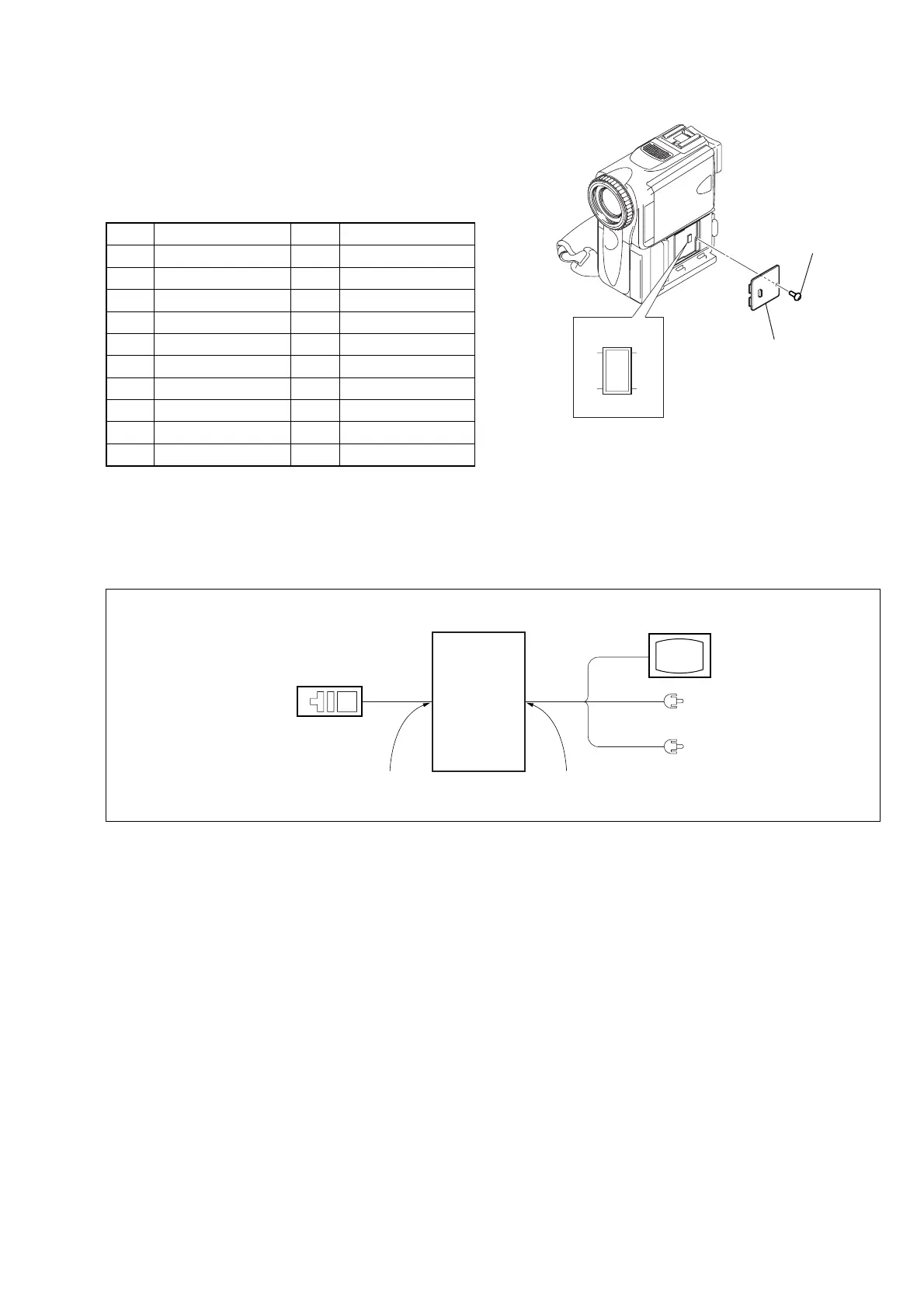
3-1-4. Connecting the Equipment
Connect the measuring instruments as shown in Fig. 5-3-2, and
perform the adjustments.
Adjustment
remote
commander
LANC jack
Main unit
AUDIO/VIDEO jack
TV monitor
VIDEO
(Yellow)
AUDIO L (White)
AUDIO R (Red)
Fig. 5-3-1
Fig. 5-3-2
CPC lid
CN1006
21
20 19
Screw