DCR-PC101/PC101E
5-37
1-5. LCD SYSTEM ADJUSTMENTS
Before perform the LCD system adjustments, check that the data
of page: 0, address: 10 is “00”.
If not, select page: 0, address: 10, and set the data “00”.
Note 1: The back light (fluorescent tube) is driven with high volt-
age AC power. Therefore, do not touch the back light
directly, otherwise you will feel an electric shock.
Note 2: Taken an extreme care not to destroy the liquid crystal
display module by static electricity when replacing it.
Note 3: Set the “LCD BRT”, “LCD COLOR” to the center with
the function settings of the touch panel.
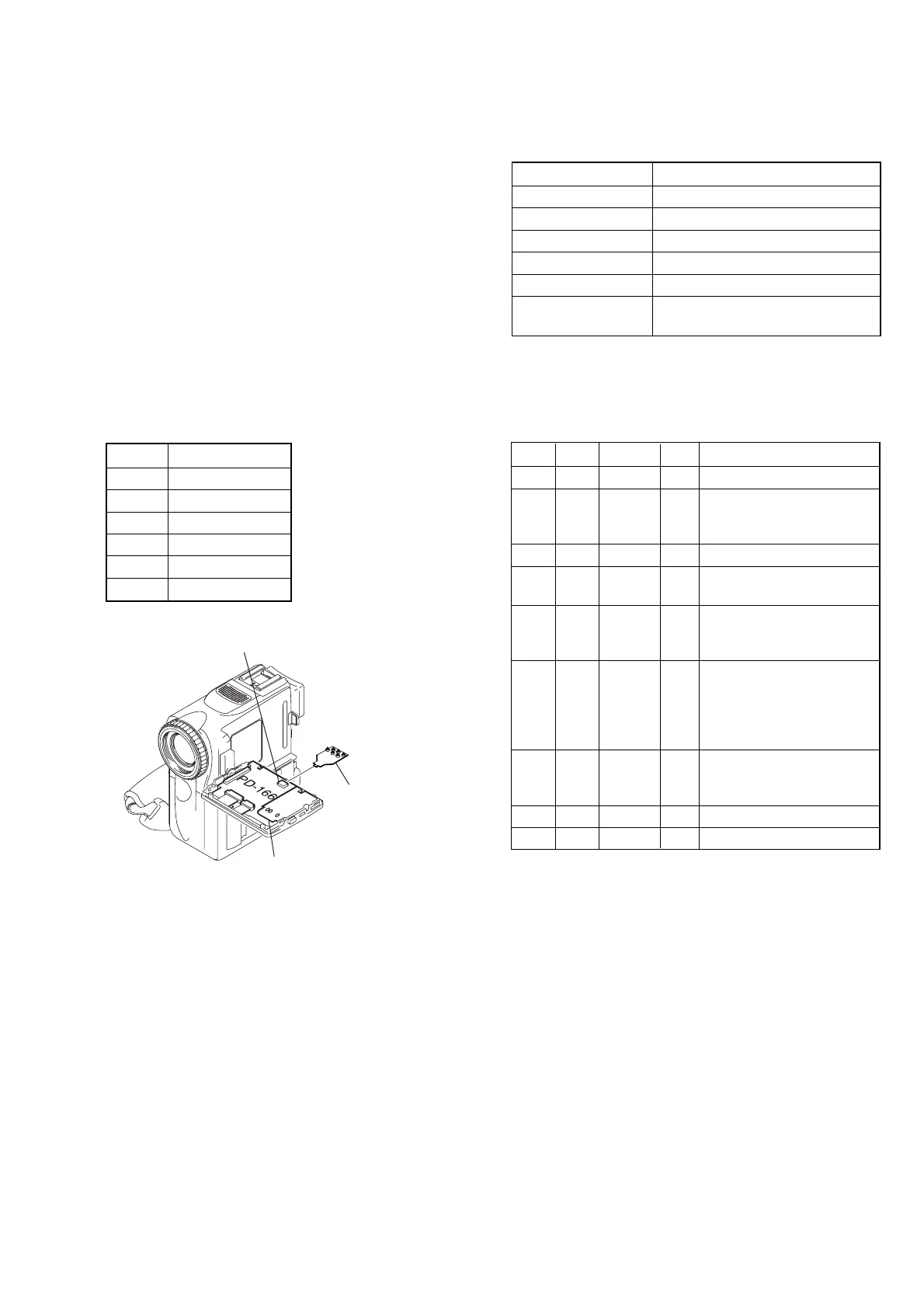
[Adjusting connector]
Most of the measuring points for adjusting the LCD system are
concentrated in CN803 of the PD-166 board.
Connect the Measuring Instruments via the CPC-jig for LCD (J-
6082-529-A).
The following table shown the Pin No. and signal name of CN803.
1. VCO Adjustment (PD-166 board)
Set the VCO free-run frequency. If deviated, the LCD screen will
be blurred.
Mode CAMERA
Subject Not required
Measurement Point Pin 4 of CN803 (HSY)
Measuring Instrument Frequency counter
Adjustment Page C
Adjustment Address 61, 62
Specified Value f = 15734 ± 30 Hz (NTSC)
f = 15625 ± 30 Hz (PAL)
Note 1: Check that the data of page: 0, address: 10 is “00”.
Note 2: NTSC model: DCR-PC101
PAL model: DCR-PC101E
Adjusting method:
Order Page Address Data Procedure
1 0 01 01
2C 61
Change the data and set the
frequency (f) to the specified
value.
3 C 61 Press PAUSE button.
4C 61
Read the data and this data is
named D
61
.
5
Convert D
61
to decimal
notation, and obtain D
61
’.
(Note 3)
6
Calculate D
62
’ using
following equations.
(decimal calculation)
D
62
’ = D
61
’ + 21
(NTSC model)
D
62
’ = D
61
’ – 21 (PAL model)
7
Convert D
62
’ to a hexadeci-
mal number, and obtain D
62
.
(Note 3, 4)
8C 62D
62
Press PAUSE button.
9 0 01 00
Note 3: Refer to table 5-4-1. “Hexadecimal-decimal conversion
table”
Note 4: If D
62
’ > 255, then D
62
= FF (NTSC model)
If D
62
’ < 0, then D
62
= 00 (PAL model)
Pin No. Signal Name
1VG
2 COM
3 GND
4 HSY
5 N.C.
6 PSIG
Fig. 5-1-17
Inverter transformer unit
CN803 of PD-166 board
CPC jig for LCD panel
(J-6082-529-A)