Customer Replaceable Units Top Cover Assembly
Page 167
© Copyright 2020 Stratasys. All rights reserved.
10. Lift and remove the cover assembly from the printer.
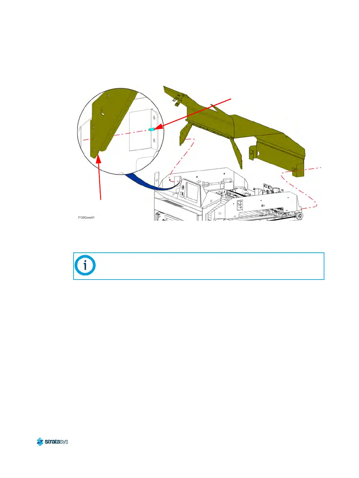
Figure 21: Top cover mounting screw locations
Installing the Top Cover
1. Transfer the latch, sensor actuator and mounting hardware from the old front cover to the
new cover assembly.
2. While holding open the front cover, loosely install the cover assembly to the top of the
p
rinter so that the buttresses engage the retaining pins on the left and right side support
brackets. See Figure 21 (page 167).
3. Using a 3 mm hex wrench, tighten the screws (4) that secure the cover assembly
b
uttresses to the left and right side support brackets. See Figure 21 (page 167).
4. Using a 5 mm hex wrench, tighten the screws (2) that secure the back cover to the top of
t
he printer frame. See Figure 21 (page 167).
5. Install the right and left side louver panels. See “
Installing the Louver Panels” (page 166).
6. Install the right and left side panels. See “
Installing the Side Panels” (page 164).
7. Install the rear panel. See “
Installing the Rear Panel” (page 161).
8. Close the top cover.
Note:
Install the sensor actuator so that it is biased toward the cover sensor inside the
printer gantry.
Support Bracket
Retaining Pin
Cover Buttress