112
S
Note If there is an Image Data Transmitter board installed, the CAN bus connects to it
rst, then to the Light Circuit Board.
CAN Bus connection in the Horizontal Arm
e brown wire is CAN+ and the clear wire is CAN-.
Note To gain access to these wires, remove the small cover next to the Central Axis.
e Central Axis rework for proper transmission of color from the in-light Cam-
era is visible by electrical tape as shown in the picture.
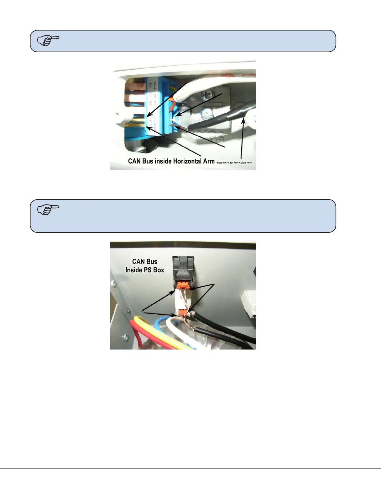
CAN Bus connection in the power supply box just inside the panel connector
e brown wire is CAN+ and the clear wire is CAN-.
To access these wires, remove the top cover from the power supply box.