Installing the Equipment
Page 2-8 Instruction Manual: evolution 5000 E5710 and E5720 Encoder
ST.TM.E10074.1
Connecting the Encoder to the AC Power Supply
WARNINGS...
1. DO NOT OVERLOAD WALL OUTLETS AND EXTENSION CORDS AS THIS CAN RESULT IN A
RISK OF FIRE OR ELECTRIC SHOCK.
2. AS NO MAINS SWITCH IS FITTED TO THIS UNIT, ENSURE THE LOCAL AC POWER SUPPLY IS
SWITCHED OFF BEFORE CONNECTING THE SUPPLY CORD.
3. THE ENCODER IS NOT FITTED WITH AN ON/OFF SWITCH. ENSURE THAT THE SOCKET-
OUTLET IS INSTALLED NEAR THE EQUIPMENT SO THAT IT IS EASILY ACCESSIBLE.
FAILURE TO ISOLATE THE EQUIPMENT PROPERLY MAY CAUSE A SAFETY HAZARD.
To connect the unit to the local ac power supply:
1. Ensure the local ac supply is switched OFF.
2. Ensure the correct fuse type and rating has been fitted to both the
equipment and the ac power cable.
3. Connect the ac power lead to the Encoder mains input connector and
then to the local mains supply.
2.5 Signal Connections For the Basic Unit
2.5.1 Introduction
All signal connectors are located at the rear panel of the Encoder. For a
detailed interface specification see Annex B, Technical Specification.
Always use the specified cables supplied for signal integrity and compliance
with EMC requirements (see Annex B, Technical Specification, Table B.19).
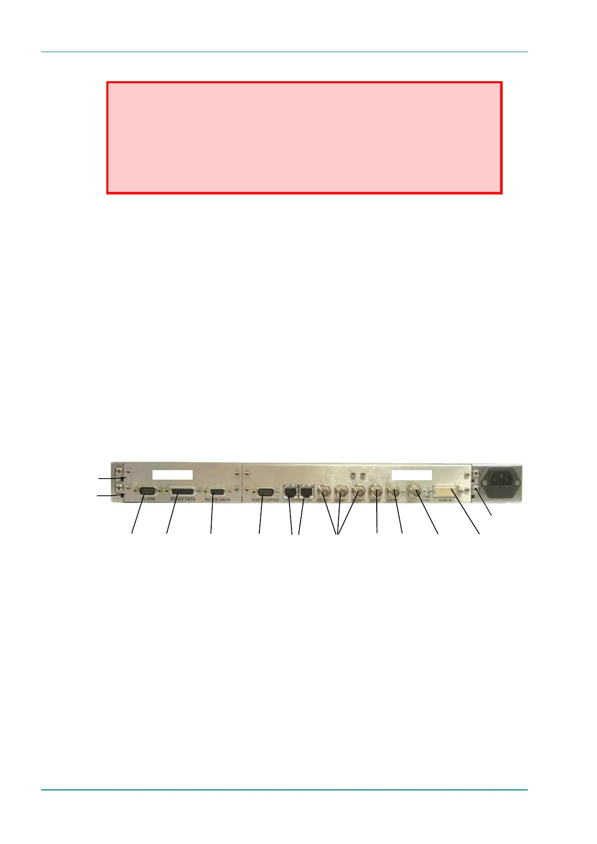
Figure 2.3: E5710 (1U) Rear Panel Component Parts and Connectors
Audio In and
Audio
Reference Out
H Sync
Composite
Video
ASI Outputs
EthernetRS-232
Data
RS-422
Data
Alarm
RS-232/
RS-485
Control
SDI In
Option Slot 1
Option Slot 2
Base Board
Option Slots 1-2
Technical Earth