Installing the Equipment
Instruction Manual: evolution 5000 E5710 and E5720 Encoder Page 2-9
ST.TM.E10074.1
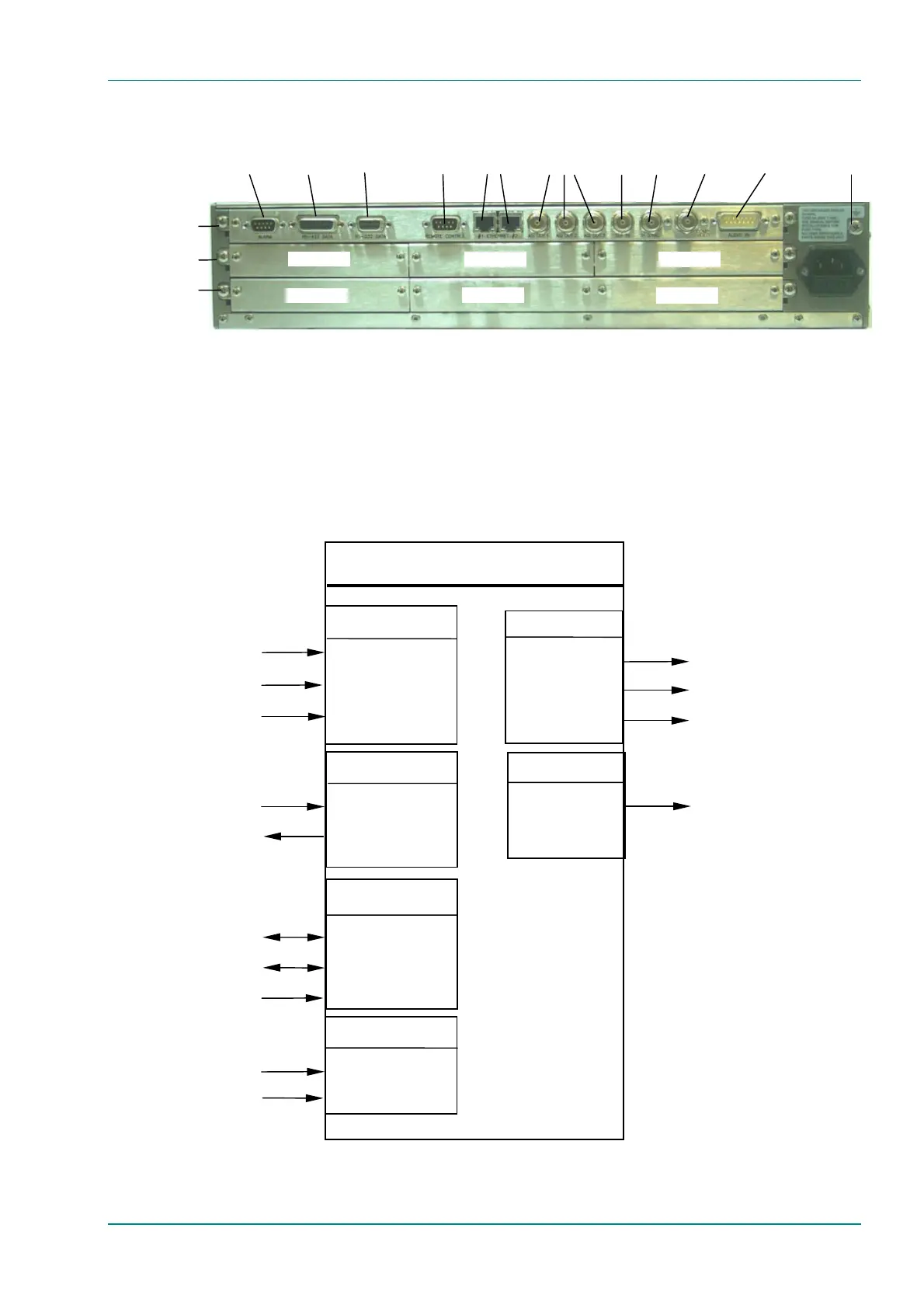
Figure 2.4: E5720 (2U) Rear Panel Component Parts and Connectors
2.5.2 Connecting Up the Basic Encoder
Once the unit has been installed in its intended operating position, it is
ready to be connected up to the rest of the system equipment
(see Figure 2.5), providing it too has been installed (see Signal
Connections for pin-out details of the connectors).
Figure 2.5: Equipment Connections for the Basic Unit
Option Slot 1
Option Slot 2
Option Slot 3
Option Slot 4 Option Slot 5
Option Slot 6
Option Slots 1-3
Audio In and
Audio
Reference Out
H Sync
Composite
Video
ASI
Outputs
RS-232
Data
RS-422
Data
Alarm
RS-232/
RS-485
Control
SDI In
Ethernet
Option Slots 4-6
Base Board
Technical
Earth
Encoder
Video Input
SDI IN
H SYNC
COMP VIDEO
Audio input
AES/EBU Reference
ETHERNET #1
ETHERNET #2
REMOTE CONTROL
Audio Input
Control
RS-232 data input
RS-422 data input
Alarm
DVB/ATSC Transport stream output
Output
Alarm
ASI OUT 1
ASI OUT 2
SI OUT 3
ALARM
10BaseT
10BaseT
RS-232/RS-485
AUDIO IN
DVB/ATSC Transport stream output
DVB/ATSC Transport stream output
Serial Digital Interface
Analogue composite video
Studio Black and Burst
Data
RS-232 DATA
RS-422 DATA