G10 Hardware Maintenance Guide 7.13.2 61
3
Blades and RTMs
Rev. 002-140228
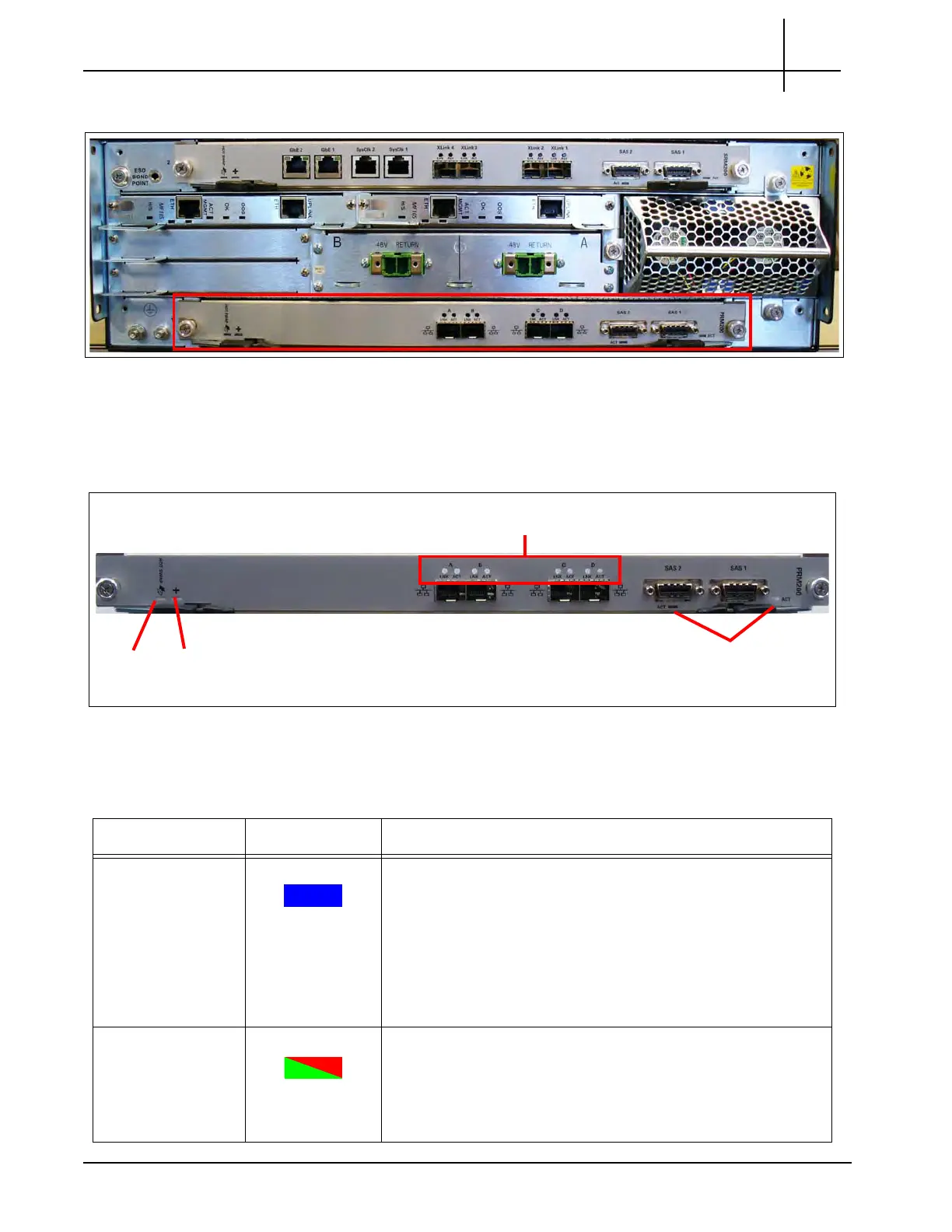
Figure 3.29 displays the PRM200/PRM300.
Figure 3.29 - PRM300/PRM200 RTM
PRM300/PRM200 LEDs
Figure 3.30 shows the RTM LED indicators.
Figure 3.30 - PRM300/PRM200 LEDs
Table 3.20 describes the PRM300/PRM200 LEDs.
Hot
Swap
LED
Health (+)
LED
Ethernet LNK and
ACT LEDs
SAS
Activity
LEDs
Table 3.20 - PRM300/PRM200 RTM LEDs
LED LED Color Description
Hot Swap BLUE Hot Swap Indicator which indicates
when it
is safe to remove
the RTM.
SOLID BLUE— The blade is in standby mode and can be
safely extracted.
BLINKING BLUE—The module is in a transition between
standby mode and operational mode.
OFF—The blade is active; do not extract it.
Health (+) GREEN or RED Indicates the health of the PRM200 RTM.
GREEN—No errors.
RED—An error occurred.
OFF—The board is not powered on.
Tektronix Communications | For Licensed Users | Unauthorized Duplication and Distribution Prohibited

 Loading...