G10 Hardware Maintenance Guide 7.13.2 62
3
Blades and RTMs
Rev. 002-140228
PRM300/PRM200 Connectors
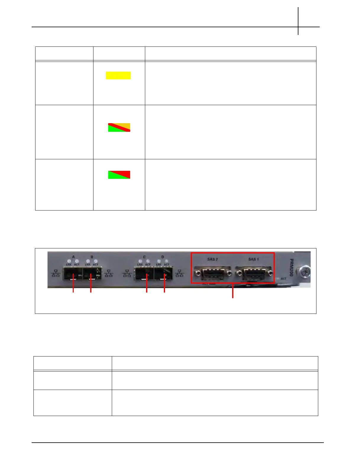
Figure 3.31 shows the RTM LED indicators.
Figure 3.31 - PRM300/PRM200 Connectors
Table 3.21 describes the PRM300/PRM200 connectors.
Ethernet ACT
LEDs
YELLOW I
ndicates Ethernet link activity.
SOLID YELLOW = The Ethernet link is up; no activity.
BLINKING YELLOW = Ethernet activity occurring.
OFF = No Ethernet link established.
Ethernet LNK
LEDs
GREEN,
AMBER, or RED
I
ndicates Ethernet link status.
GREEN = The Ethernet link is up at 10 Gb speed.
AMBER = The Ethernet link is up at 1 Gb speed.
RED = The Ethernet link is up at 100M speed.
OFF = No link established.
ACT (SAS) GREEN or RED SAS activity LED
Two SAS activity LEDs, one for each SAS port.
GREEN—No errors; SAS link is up.
RED—Error occurred.
OFF—No SAS link established.
Table 3.20 - PRM300/PRM200 RTM LEDs (Continued)
LE
D LED Color Description
ETH A
SAS Ports
ETH B
ETH C ETH D
Table 3.21 - PRM300/PRM200 Connectors
Connector Description
ETH A (Primary Interface) Primary 1G Ethernet LAN (uplink to server). Supports 10G/1G/100Mb;
no
rm
al usage is 1G/100Mb for OAM.
ETH B Redundant Primary 1G Ethernet LAN (uplink to server). Only used for
redu
ndant Primary LAN configuration. Supports 10G/1G/100Mb; normal
usage is 1G/100Mb for OAM.
Tektronix Communications | For Licensed Users | Unauthorized Duplication and Distribution Prohibited

 Loading...