G10 Hardware Maintenance Guide 7.13.2 69
3
Blades and RTMs
Rev. 002-140228
Table 3.25 describes the PRM100 LEDs.
PRM100 Connectors
Table 3.26 describes the PRM100 connectors.
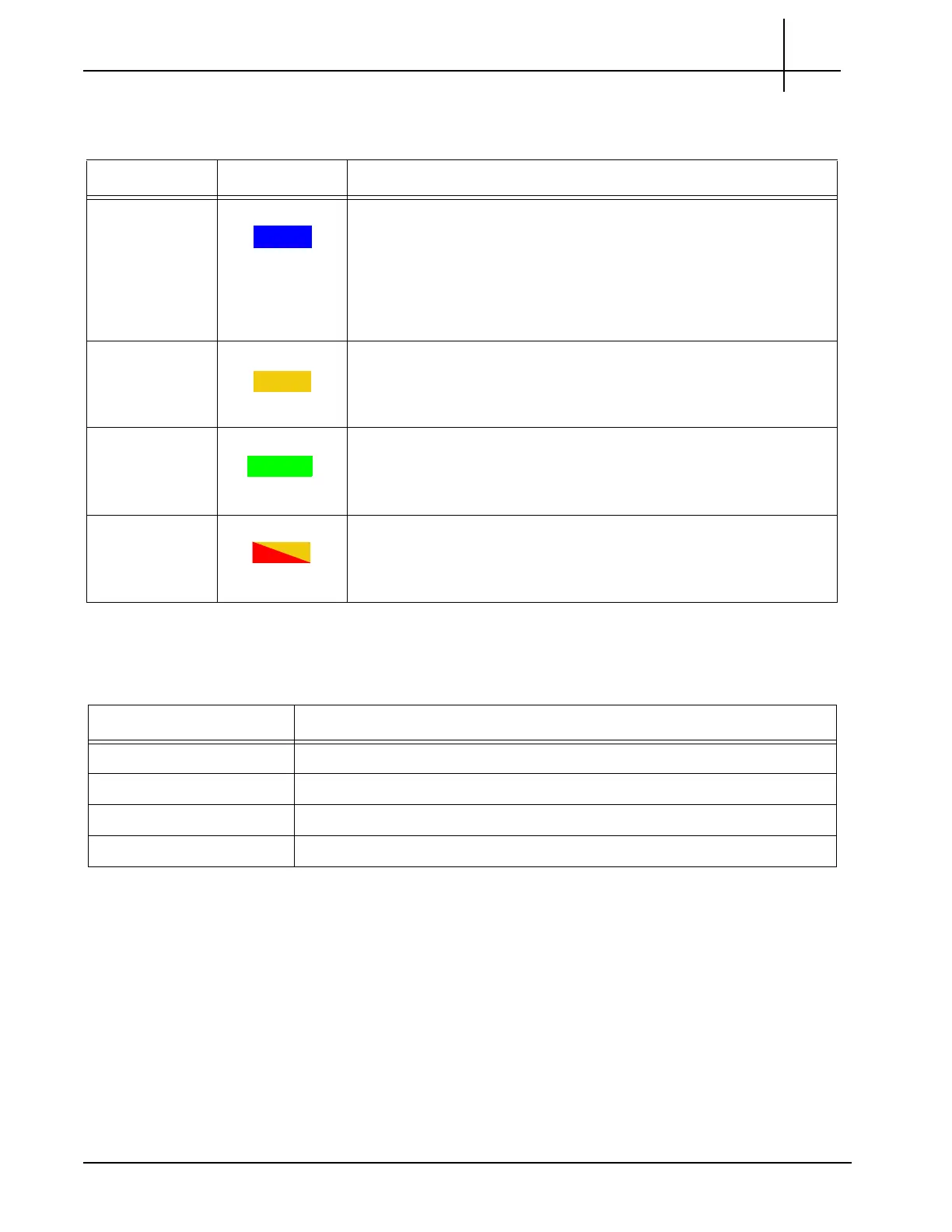
Table 3.25 - PRM100 LEDs
LED LED Color Description
H/S BLUE Hot swap indicator.
SOLID BLUE—Ready for hot swap.
LONG BLUE BLINK—Activating the module after insertion short.
BLUE BLINK—Preparing for the hot swap.
OFF—No hot-swap activity is in progress.
ACT AMBER Indicates HDD activity.
BLINKING AMBER—HDD activity.
OFF—No activity.
PWR GREEN Indicates power status.
GREEN—Power to the RTM is normal.
OFF—The RTM is not powered or is in the hot-swap process.
OOS RED or AMBER Indicates the device is out of service.
RED or AMBER—The RTM is out of service.
OFF—The RTM is operating normally.
Table 3.26 - PRM100 Connectors
Connector Description
SFP Sockets (two) Not used.
RS-232 Serial Port Not used.
SAS Ports (two) Provides connectivity to storage subsystem.
USB Port Not used.
Tektronix Communications | For Licensed Users | Unauthorized Duplication and Distribution Prohibited
 Loading...
