Register Bit Definitions
www.ti.com
Table 4-46. GPIO XNMI Interrupt Select (GPIOXNMISEL) Register Field Descriptions
Bits Field Value Description
(1)
15-5 Reserved Reserved
4-0 GPIOSEL Select which port A GPIO signal (GPIO0 - GPIO31) will be used as the XNMI interrupt source. In
addition you can configure the interrupt in the XNMICR register described in Section 6.6 .
00000 Select the GPIO0 pin as the XNMI interrupt source (default)
00001 Select the GPIO1 pin as the XNMI interrupt source
. . . . . .
11110 Select the GPIO30 pin as the XNMI interrupt source
11111 Select the GPIO31 pin as the XNMI interrupt source
(1)
This register is EALLOW protected. See Section 5.2 for more information.
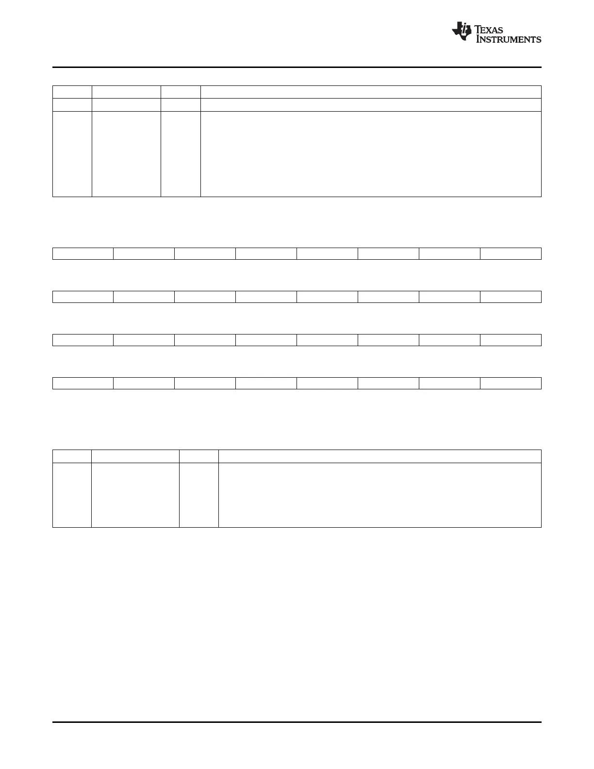
Figure 4-33. GPIO Low Power Mode Wakeup Select (GPIOLPMSEL) Register
31 30 29 28 27 26 25 24
GPIO31 GPIO30 GPIO29 GPIO28 GPIO27 GPIO26 GPIO25 GPIO24
R/W-0 R/W-0 R/W-0 R/W-0 R/W-0 R/W-0 R/W-0 R/W-0
23 22 21 20 19 18 17 16
GPIO23 GPIO22 GPIO21 GPIO20 GPIO19 GPIO18 GPIO17 GPIO16
R/W-0 R/W-0 R/W-0 R/W-0 R/W-0 R/W-0 R/W-0 R/W-0
15 14 13 12 11 10 9 8
GPIO15 GPIO14 GPIO13 GPIO12 GPIO11 GPIO10 GPIO9 GPIO8
R/W-0 R/W-0 R/W-0 R/W-0 R/W-0 R/W-0 R/W-0 R/W-0
7 6 5 4 3 2 1 0
GPIO7 GPIO6 GPIO5 GPIO4 GPIO3 GPIO2 GPIO1 GPIO0
R/W-0 R/W-0 R/W-0 R/W-0 R/W-0 R/W-0 R/W-0 R/W-0
LEGEND: R/W = Read/Write; R = Read only; - n = value after reset
Table 4-47. GPIO Low Power Mode Wakeup Select (GPIOLPMSEL) Register Field Descriptions
Bits Field Value Description
(1)
31-0 GPIO31 - GPIO0 Low Power Mode Wakeup Selection. Each bit in this register corresponds to one GPIO port
A pin (GPIO0 - GPIO31) as shown in Figure 4-33 .
0 If the bit is cleared, the signal on the corresponding pin will have no effect on the HALT and
STANDBY low power modes.
1 If the respective bit is set to 1, the signal on the corresponding pin is able to wake the
device from both HALT and STANDBY low power modes.
(1)
This register is EALLOW protected. See Section 5.2 for more information.
108 General-Purpose Input/Output (GPIO) SPRUFB0C – September 2007 – Revised May 2009
Submit Documentation Feedback
 Loading...