www.ti.com
Watchdog Block
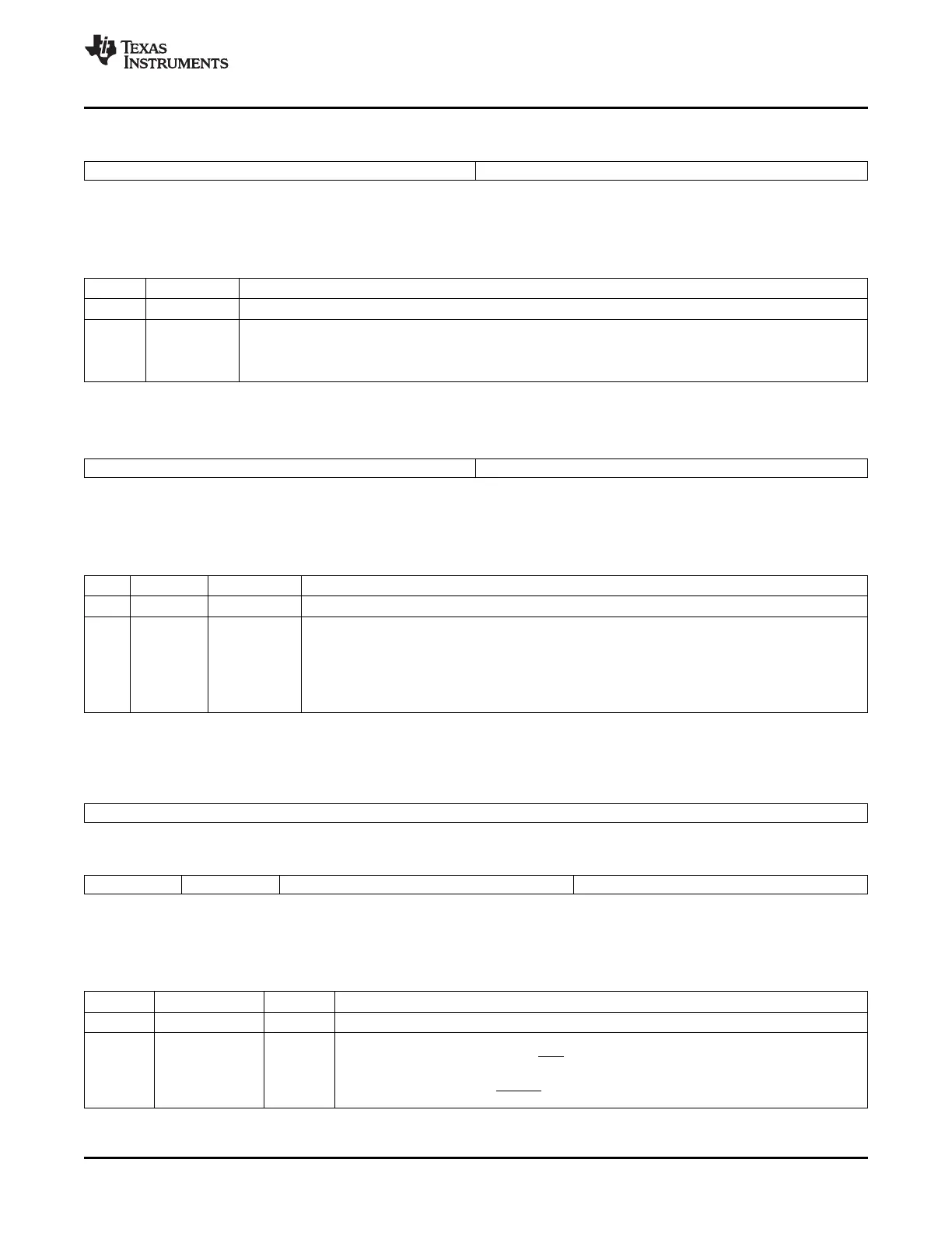
Figure 3-16. Watchdog Counter Register (WDCNTR)
15 8 7 0
Reserved WDCNTR
R-0 R-0
LEGEND: R/W = Read/Write; R = Read only; - n = value after reset
Table 3-15. Watchdog Counter Register (WDCNTR) Field Descriptions
Bits Field Description
15-8 Reserved Reserved
7-0 WDCNTR These bits contain the current value of the WD counter. The 8-bit counter continually increments at the
watchdog clock (WDCLK), rate. If the counter overflows, then the watchdog initiates a reset. If the WDKEY
register is written with a valid combination, then the counter is reset to zero. The watchdog clock rate is
configured in the WDCR register.
Figure 3-17. Watchdog Reset Key Register (WDKEY)
15 8 7 0
Reserved WDKEY
R-0 R/W-0
LEGEND: R/W = Read/Write; R = Read only; - n = value after reset
Table 3-16. Watchdog Reset Key Register (WDKEY) Field Descriptions
Bits Field Value Description
(1)
15-8 Reserved Reserved
7-0 WDKEY Refer to Table 3-13 for examples of different WDKEY write sequences.
0x55 + 0xAA Writing 0x55 followed by 0xAA to WDKEY causes the WDCNTR bits to be cleared.
Other value Writing any value other than 0x55 or 0xAA causes no action to be generated. If any value other than
0xAA is written after 0x55, then the sequence must restart with 0x55.
Reads from WDKEY return the value of the WDCR register.
(1)
This register is EALLOW protected. See Section 5.2 for more information.
Figure 3-18. Watchdog Control Register (WDCR)
15 8
Reserved
7 6 5 3 2 0
WDFLAG WDDIS WDCHK WDPS
R/W1C-0 R/W-0 R/W-0 R/W-0
LEGEND: R/W = Read/Write; R = Read only; - n = value after reset
Table 3-17. Watchdog Control Register (WDCR) Field Descriptions
Bits Field Value Description
(1)
15-8 Reserved Reserved
7 WDFLAG Watchdog reset status flag bit
0 The reset was caused either by the XRS pin or because of power-up. The bit remains latched
until you write a 1 to clear the condition. Writes of 0 are ignored.
1 Indicates a watchdog reset ( WDRST) generated the reset condition. .
(1)
This register is EALLOW protected. See Section 5.2 for more information.
SPRUFB0C – September 2007 – Revised May 2009 Clocking 59
Submit Documentation Feedback
 Loading...