Clocking and System Control
www.ti.com
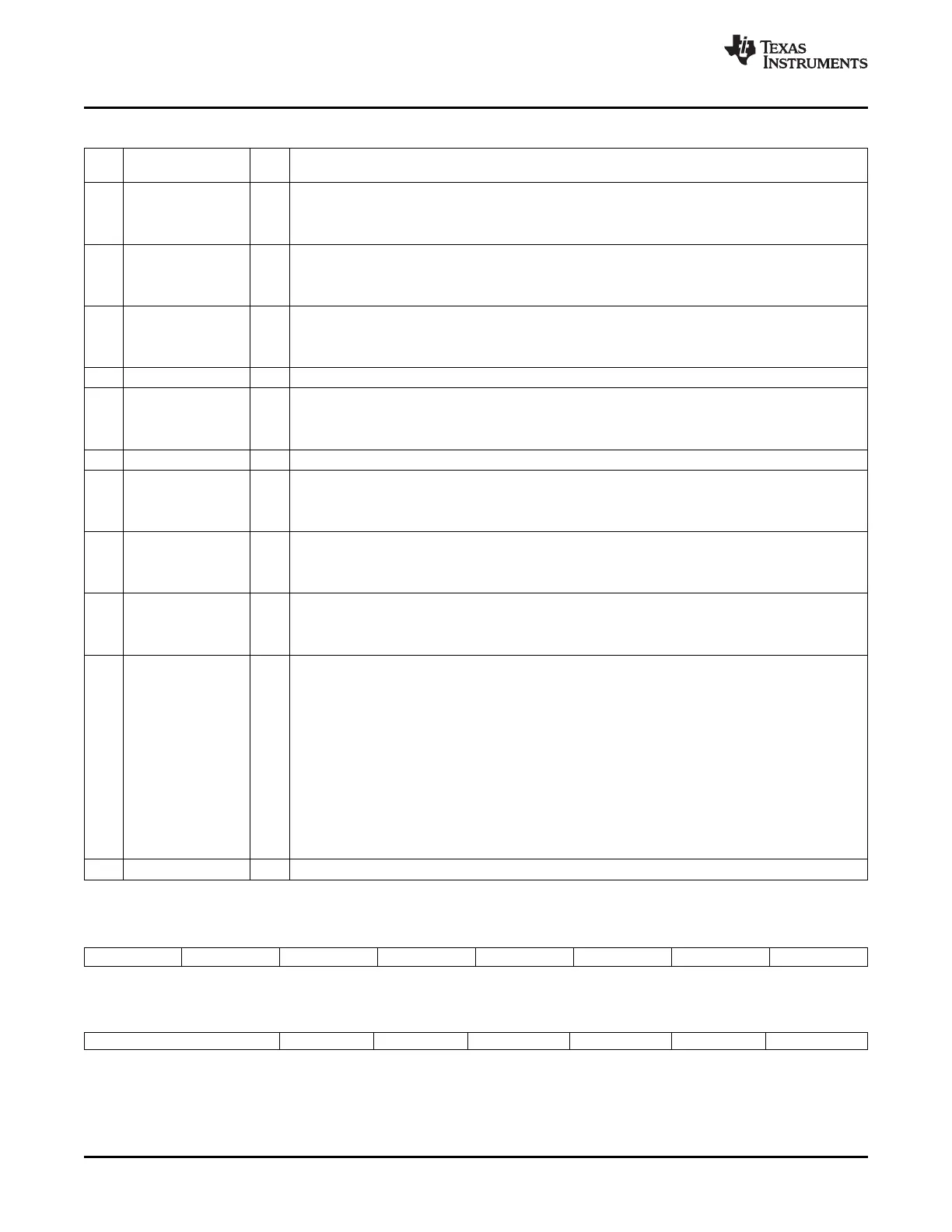
Table 3-2. Peripheral Clock Control 0 Register (PCLKCR0) Field Descriptions (continued)
Bit Field Valu Description
(1)
e
12 MCBSPAENCLK McBSP-A Clock Enable
0 The McBSP-A module is not clocked. (default)
1 The McBSP-A module is clocked by the low-speed clock (LSPCLK).
11 SCIBENCLK SCI-B clock enable
0 SCI-B module is not clocked. (default)
(2)
1 The SCI-B module is clocked by the low-speed clock (LSPCLK).
10 SCIAENCLK SCI-A clock enable
0 The SCI-A module is not clocked. (default)
(2)
1 The SCI-A module is clocked by the low-speed clock (LSPCLK).
9 Reserved 0 Reserved
8 SPIAENCLK SPI-A clock enable
0 The SPI-A module is not clocked. (default)
(2)
1 The SPI-A module is clocked by the low-speed clock (LSPCLK).
7:6 Reserved 0 Reserved
5 SCICENCLK SCI-C clock enable. This bit is reserved on devices without the SCI-C module.
(3)
0 The SCI-C module is not clocked. (default)
1 The SCI-C module is clocked by the low-speed clock (LSPCLK).
4 I2CAENCLK I2C clock enable
0 The I2C module is not clocked. (default)
(2)
1 The I2C module is clocked by SYSCLKOUT.
3 ADCENCLK ADC clock enable
0 The ADC is not clocked. (default)
(2)
1 The ADC module is clocked by the high-speed clock (HSPCLK)
2 TBCLKSYNC ePWM Module Time Base Clock (TBCLK) Sync: Allows the user to globally synchronize all enabled
ePWM modules to the time base clock (TBCLK):
0 The TBCLK (Time Base Clock) within each enabled ePWM module is stopped. (default). If, however,
the ePWM clock enable bit is set in the PCLKCR1 register, then the ePWM module will still be clocked
by SYSCLKOUT even if TBCLKSYNC is 0.
1 All enabled ePWM module clocks are started with the first rising edge of TBCLK aligned. For perfectly
synchronized TBCLKs, the prescaler bits in the TBCTL register of each ePWM module must be set
identically. The proper procedure for enabling ePWM clocks is as follows:
• Enable ePWM module clocks in the PCLKCR1 register.
• Set TBCLKSYNC to 0.
• Configure prescaler values and ePWM modes.
• Set TBCLKSYNC to 1.
1-0 Reserved Reserved
Figure 3-3. Peripheral Clock Control 1 Register (PCLKCR1)
15 14 13 12 11 10 9 8
EQEP2ENCLK EQEP1ENCLK ECAP6ENCLK ECAP5ENCLK ECAP4ENCLK ECAP3ENCLK ECAP2ENCLK ECAP1ENCLK
R/W-0 R/W-0 R/W-0 R/W-0 R/W-0 R/W-0 R/W-0 R/W-0
7 6 5 4 3 2 1 0
Reserved EPWM6ENCLK EPWM5ENCLK EPWM4ENCLK EPWM3ENCLK EPWM2ENCLK EPWM1ENCLK
R-0 R/W-0 R/W-0 R/W-0 R/W-0 R/W-0 R/W-0
LEGEND: R/W = Read/Write; R = Read only; - n = value after reset
Clocking40 SPRUFB0C – September 2007 – Revised May 2009
Submit Documentation Feedback
 Loading...