Start
Stage A
PIEIFRx.y=1
?
Wait for any
PIEIFRx.y=1
No
Wait for
PIEIERx.y=1
Stage B
PIEIERx.y=1
?
No
PIEACKx=0
Stage C
?
No
Wait for
S/W to clear
PIEACKx bit=0
Yes
Yes
Yes
Hardware sets
PIEACKx=1
Stage D
Interrupt request
sent to 28x CPU
on INTx
Interrupts
to CPU
Stage E
IFRx bit set 1
Yes
Stage G
INTM bit=0
?
No
Yes
IERx bit=1
Stage F
?
No
Stage H
CPU responds
IFRx=0, IERx=0
INTM=1, EALLOW=0
Context Save performed
Stage I
Vector fetched from the PIE
(A)
PIEIFRx.y is cleared
CPU branches to ISR
Stage J
Interrupt service routine responds
Write 1 to PIEACKx bit to clear
to enable other interrupts in
PIEIFRx group
Re-enable interrupts, INTM=0
Return
End
CPU interrupt controlPIE interrupt control
Overview of the PIE Controller
www.ti.com
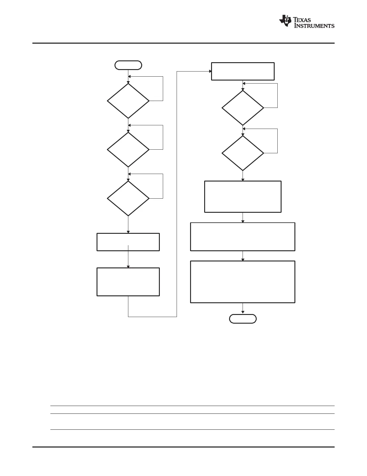
Figure 6-2. Typical PIE/CPU Interrupt Response - INTx.y
A For multiplexed interrupts, the PIE responds with the highest priority interrupt that is both flagged and enabled. If
there is no interrupt both flagged and enabled, then the highest priority interrupt within the group (INTx.1 where x is
the PIE group) is used. See Section Section 6.3.3 for details.
As shown in Table 6-1 , the requirements for enabling the maskable interrupt at the CPU level depends on
the interrupt handling process being used. In the standard process, which happens most of the time, the
DBGIER register is not used. When the 28x is in real-time emulation mode and the CPU is halted, a
different process is used. In this special case, the DBGIER is used and the INTM bit is ignored. If the DSP
is in real-time mode and the CPU is running, the standard interrupt-handling process applies.
Table 6-1. Enabling Interrupt
Interrupt Handling Process Interrupt Enabled If …
Standard INTM = 0 and bit in IER is 1
DSP in real-time mode and halted Bit in IER is 1 and DBGIER is 1
Peripheral Interrupt Expansion (PIE)124 SPRUFB0C – September 2007 – Revised May 2009
Submit Documentation Feedback
 Loading...