6.6 External Interrupt Control Registers
External Interrupt Control Registers
www.ti.com
Seven external interrupts, XINT1 –XINT7 are supported. XINT13 is multiplexed with one non-maskable
interrupt XNMI. Each of these external interrupts can be selected for negative or positive edge triggered
and can also be enabled or disabled (including XNMI). The masked interrupts also contain a 16-bit free
running up counter that is reset to zero when a valid interrupt edge is detected. This counter can be used
to accurately time stamp the interrupt.
XINT1CR through XINT 7CR are identical except for the interrupt number; therefore, Figure 6-14 and
Table 6-14 represent registers for external interrupts 1 through 7 as XINT nCR where n = the interrupt
number.
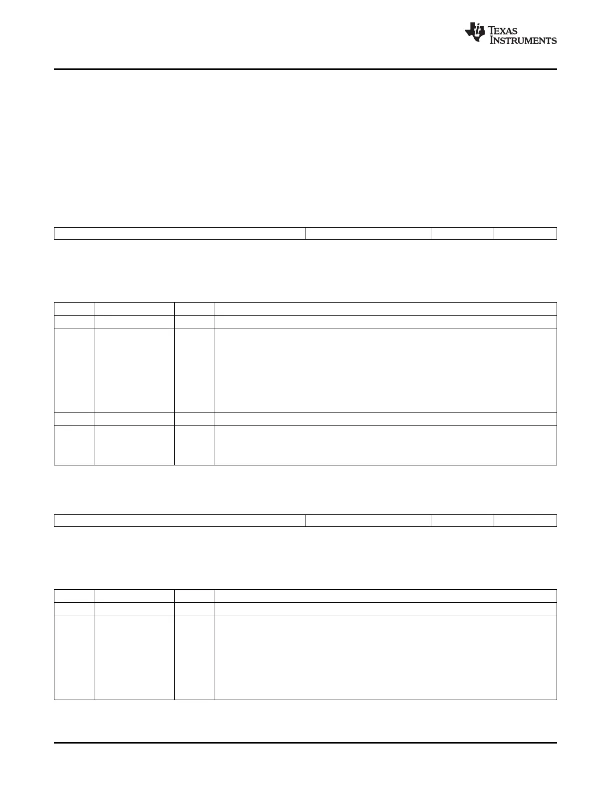
Figure 6-14. External Interrupt n Control Register (XINT nCR)
15 4 3 2 1 0
Reserved Polarity Reserved Enable
R-0 R/W-0 R-0 R/W-0
LEGEND: R/W = Read/Write; R = Read only; - n = value after reset
Table 6-14. External Interrupt n Control Register (XINT nCR) Field Descriptions
Bits Field Value Description
15-4 Reserved Reads return zero; writes have no effect.
3-2 Polarity This read/write bit determines whether interrupts are generated on the rising edge or the
falling edge of a signal on the pin.
00 Interrupt generated on a falling edge (high-to-low transition)
01 Interrupt generated on a rising edge (low-to-high transition)
10 Interrupt is generated on a falling edge (high-to-low transition)
11 Interrupt generated on both a falling edge and a rising edge (high-to-low and low-to-high
transition)
1 Reserved Reads return zero; writes have no effect
0 Enable This read/write bit enables or disables external interrupt XINT n.
0 Disable interrupt
1 Enable interrupt
Figure 6-15. External NMI Interrupt Control Register (XNMICR) — Address 7077h
15 4 3 2 1 0
Reserved Polarity Select Enable
R-0 R/W-0 R-0 R/W-0
LEGEND: R/W = Read/Write; R = Read only; - n = value after reset
Table 6-15. External NMI Interrupt Control Register (XNMICR) Field Descriptions
Bits Field Value Description
15-4 Reserved Reads return zero; writes have no effect.
3-2 Polarity This read/write bit determines whether interrupts are generated on the rising edge or the
falling edge of the signal on the pin.
00 Interrupt generated on a falling edge (high-to-low transition)
01 Interrupt generated on a rising edge low-to-high transition)
10 Interrupt is generated on a falling edge (high to low transition)
11 Interrupt generated on both a falling edge and a rising edge (high to low and low to high
transition)
148 Peripheral Interrupt Expansion (PIE) SPRUFB0C – September 2007 – Revised May 2009
Submit Documentation Feedback
 Loading...