6.1 Overview of the PIE Controller
6.1.1 Interrupt Operation Sequence
INT12
MUX
INT11
INT2
INT1
CPU
(Enable)(Flag)
INTx
INTx.8
PIEIERx(8:1) PIEIFRx(8:1)
MUX
INTx.7
INTx.6
INTx.5
INTx.4
INTx.3
INTx.2
INTx.1
From
Peripherals or
External
Interrupts
(Enable) (Flag)
IER(12:1)IFR(12:1)
Global
Enable
INTM
1
0
PIEACKx
(Enable/Flag)
Overview of the PIE Controller
www.ti.com
The 28x CPU supports one nonmaskable interrupt (NMI) and 16 maskable prioritized interrupt requests
(INT1-INT14, RTOSINT, and DLOGINT) at the CPU level. The 28x devices have many peripherals and
each peripheral is capable of generating one or more interrupts in response to many events at the
peripheral level. Because the CPU does not have sufficient capacity to handle all peripheral interrupt
requests at the CPU level, a centralized peripheral interrupt expansion (PIE) controller is required to
arbitrate the interrupt requests from various sources such as peripherals and other external pins.
The PIE vector table is used to store the address (vector) of each interrupt service routine (ISR) within the
system. There is one vector per interrupt source including all MUXed and nonMUXed interrupts. You
populate the vector table during device initialization and you can update it during operation.
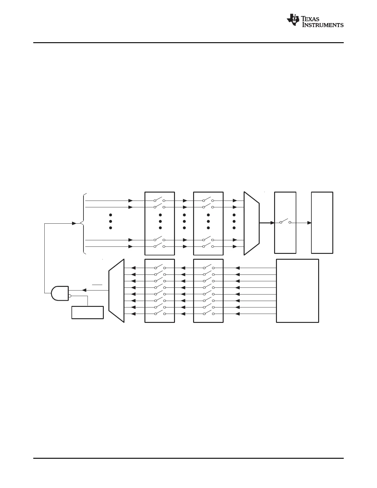
Figure 6-1 shows an overview of the interrupt operation sequence for all multiplexed PIE interrupts.
Interrupt sources that are not multiplexed are fed directly to the CPU.
Figure 6-1. Overview: Multiplexing of Interrupts Using the PIE Block
• Peripheral Level
An interrupt-generating event occurs in a peripheral. The interrupt flag (IF) bit corresponding to that
event is set in a register for that particular peripheral.
If the corresponding interrupt enable (IE) bit is set, the peripheral generates an interrupt request to the
PIE controller. If the interrupt is not enabled at the peripheral level, then the IF remains set until
cleared by software. If the interrupt is enabled at a later time, and the interrupt flag is still set, the
interrupt request is asserted to the PIE.
Interrupt flags within the peripheral registers must be manually cleared. See the peripheral reference
guide for a specific peripheral for more information.
• PIE Level
The PIE block multiplexes eight peripheral and external pin interrupts into one CPU interrupt. These
interrupts are divided into 12 groups: PIE group 1 - PIE group 12. The interrupts within a group are
multiplexed into one CPU interrupt. For example, PIE group 1 is multiplexed into CPU interrupt 1
(INT1) while PIE group 12 is multiplexed into CPU interrupt 12 (INT12). Interrupt sources connected to
the remaining CPU interrupts are not multiplexed. For the nonmultiplexed interrupts, the PIE passes
122 Peripheral Interrupt Expansion (PIE) SPRUFB0C – September 2007 – Revised May 2009
Submit Documentation Feedback
 Loading...