3.4 Watchdog Block
/512
OSCCLK
WDCR (WDPS(2:0))
WDCLK
WDCNTR(7:0)
WDKEY(7:0)
Good Key
1 0 1
WDCR (WDCHK(2:0))
Bad
WDCHK
Key
WDCR (WDDIS)
Clear Counter
SCSR (WDENINT)
Watchdog
Prescaler
Generate
Output Pulse
(512 OSCCLKs)
8-Bit
Watchdog
Counter
CLR
WDRST
WDINT
Watchdog
55 + AA
Key Detector
XRS
Core-reset
WDRST
(A)
Internal
Pullup
www.ti.com
Watchdog Block
Table 3-12. Low Power Mode Control 0 Register (LPMCR0) Field Descriptions (continued)
Bits Field Value Description
(1)
1-0 LPM
(2)
These bits set the low power mode for the device.
00 Set the low power mode to IDLE (default)
01 Set the low power mode to STANDBY
10 Set the low power mode to HALT
(3)
11 Set the low power mode to HALT
(3)
(2)
The low power mode bits (LPM) only take effect when the IDLE instruction is executed. Therefore, you must set the LPM bits to the
appropriate mode before executing the IDLE instruction.
(3)
If you try to enter HALT mode when the device is already operating in limp mode then the device may not properly enter HALT. The
device may instead enter STANDBY mode or may hang and you may not be able to exit HALT mode. For this reason, always check that
the PLLSTS[MCLKSTS] bit = 0 before entering HALT mode.
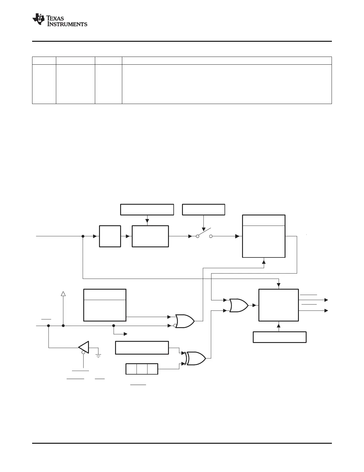
The watchdog module generates an output pulse, 512 oscillator-clocks (OSCCLK) wide whenever the
8-bit watchdog up counter has reached its maximum value. To prevent this, the user can either disable the
counter or the software must periodically write a 0x55 + 0xAA sequence into the watchdog key register
which resets the watchdog counter. Figure 3-14 shows the various functional blocks within the watchdog
module.
Figure 3-14. Watchdog Module
A The WDRST and XRS signals are driven low for 512 OSCCLK cycles when a watchdog reset occurs. Likewise, if the
watchdog interrupt is enabled, the WDINT signal will be driven low for 512 OSCCLK cycles when an interrupt occurs.
Watchdog is not functional and cannot generate a reset when OSCCLK is not present.
SPRUFB0C – September 2007 – Revised May 2009 Clocking 55
Submit Documentation Feedback
 Loading...