3.5 32-Bit CPU Timers 0/1/2
Borrow
Reset
Timer reload
SYSCLKOUT
TCR.4
(Timer start status)
TINT
16-bit timer divide-down
TDDRH:TDDR
32-bit timer period
PRDH:PRD
32-bit counter
TIMH:TIM
16-bit prescale counter
PSCH:PSC
Borrow
32-Bit CPU Timers 0/1/2
www.ti.com
Table 3-17. Watchdog Control Register (WDCR) Field Descriptions (continued)
Bits Field Value Description
(1)
6 WDDIS Watchdog disable. On reset, the watchdog module is enabled.
0 Enables the watchdog module. WDDIS can be modified only if the WDOVERRIDE bit in the
SCSR register is set to 1. (default)
1 Disables the watchdog module.
5-3 WDCHK Watchdog check.
0,0,0 You must ALWAYS write 1,0,1 to these bits whenever a write to this register is performed
unless the intent is to reset the device via software.
other If the watchdog is enabled, then writing any other value causes an immediate device reset or
watchdog interrupt to be taken. These three bits always read back as zero (0, 0, 0). This
feature can be used to generate a software reset of the DSP.
2-0 WDPS Watchdog pre-scale. These bits configure the watchdog counter clock (WDCLK) rate relative
to OSCCLK/512:
000 WDCLK = OSCCLK/512/1 (default)
001 WDCLK = OSCCLK/512/1
010 WDCLK = OSCCLK/512/2
011 WDCLK = OSCCLK/512/4
100 WDCLK = OSCCLK/512/8
101 WDCLK = OSCCLK/512/16
110 WDCLK = OSCCLK/512/32
111 WDCLK = OSCCLK/512/64
When the XRS line is low, the WDFLAG bit is forced low. The WDFLAG bit is only set if a rising edge on
WDRST signal is detected (after synch and an 8192 SYSCLKOUT cycle delay) and the XRS signal is
high. If the XRS signal is low when WDRST goes high, then the WDFLAG bit remains at 0. In a typical
application, the WDRST signal connects to the XRS input. Hence to distinguish between a watchdog reset
and an external device reset, an external reset must be longer in duration then the watchdog pulse.
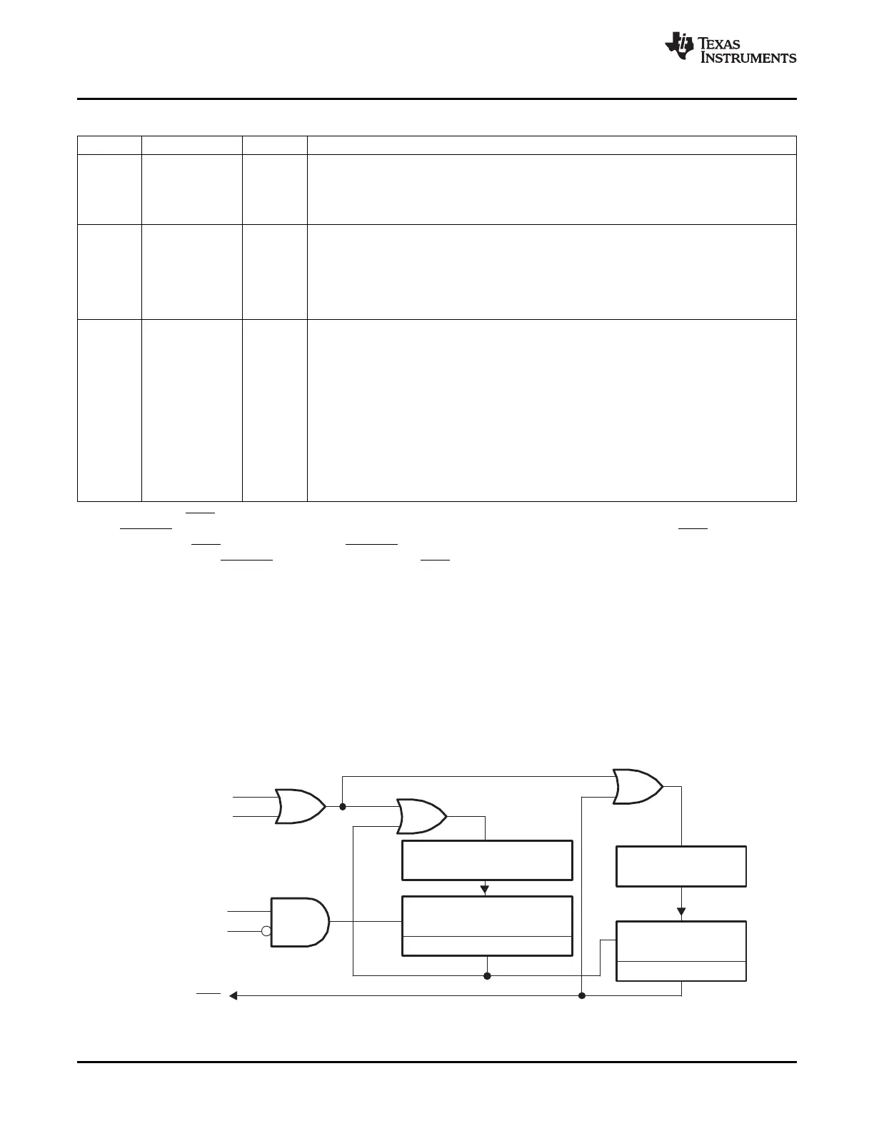
This section describes the three 32-bit CPU-timers (Figure 3-19 ) (TIMER0/1/2).
CPU-Timer 0 and CPU-Timer 1 can be used in user applications. Timer 2 is reserved for DSP-BIOS. If the
application is not using DSP-BIOS, then Timer 2 can be used in the application.
The CPU-timer interrupt signals (TINT0, TINT1, TINT2) are connected as shown in Figure 3-20 .
Figure 3-19. CPU-Timers
60 Clocking SPRUFB0C – September 2007 – Revised May 2009
Submit Documentation Feedback
 Loading...