6.5.1 PIE Interrupt Flag Registers
6.5.2 PIE Interrupt Enable Registers
www.ti.com
PIE Interrupt Registers
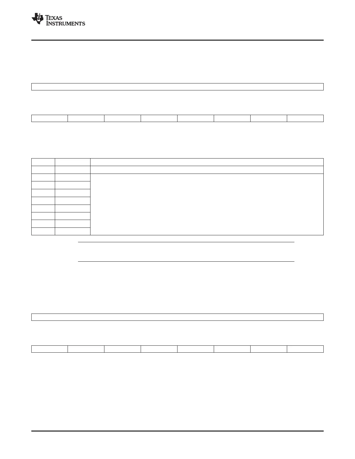
There are twelve PIEIFR registers, one for each CPU interrupt used by the PIE module (INT1-INT12).
Figure 6-9. PIEIFRx Register (x = 1 to 12)
15 8
Reserved
R-0
7 6 5 4 3 2 1 0
INTx.8 INTx.7 INTx.6 INTx.5 INTx.4 INTx.3 INTx.2 INTx.1
R/W-0 R/W-0 R/W-0 R/W-0 R/W-0 R/W-0 R/W-0 R/W-0
LEGEND: R/W = Read/Write; R = Read only; - n = value after reset
Table 6-9. PIEIFRx Register Field Descriptions
Bits Field Description
15-8 Reserved Reserved
7 INTx.8 These register bits indicate whether an interrupt is currently active. They behave very much like the CPU
interrupt flag register. When an interrupt is active, the respective register bit is set. The bit is cleared when the
6 INTx.7
interrupt is serviced or by writing a 0 to the register bit. This register can also be read to determine which
5 INTx.6
interrupts are active or pending. x = 1 to 12. INTx means CPU INT1 to INT12
4 INTx.5 The PIEIFR register bit is cleared during the interrupt vector fetch portion of the interrupt processing.
3 INTx.4 Hardware has priority over CPU accesses to the PIEIFR registers.
2 INTx.3
1 INTx.2
0 INTx.1
Note: Never clear a PIEIFR bit. An interrupt may be lost during the read-modify-write operation.
See Section Section 6.3.1 for a method to clear flagged interrupts.
There are twelve PIEIER registers, one for each CPU interrupt used by the PIE module (INT1-INT12).
Figure 6-10. PIEIERx Register (x = 1 to 12)
15 8
Reserved
R-0
7 6 5 4 3 2 1 0
INTx.8 INTx.7 INTx.6 INTx.5 INTx.4 INTx.3 INTx.2 INTx.1
R/W-0 R/W-0 R/W-0 R/W-0 R/W-0 R/W-0 R/W-0 R/W-0
LEGEND: R/W = Read/Write; R = Read only; - n = value after reset
SPRUFB0C – September 2007 – Revised May 2009 Peripheral Interrupt Expansion (PIE) 141
Submit Documentation Feedback
 Loading...