6.5.3 CPU Interrupt Flag Register (IFR)
PIE Interrupt Registers
www.ti.com
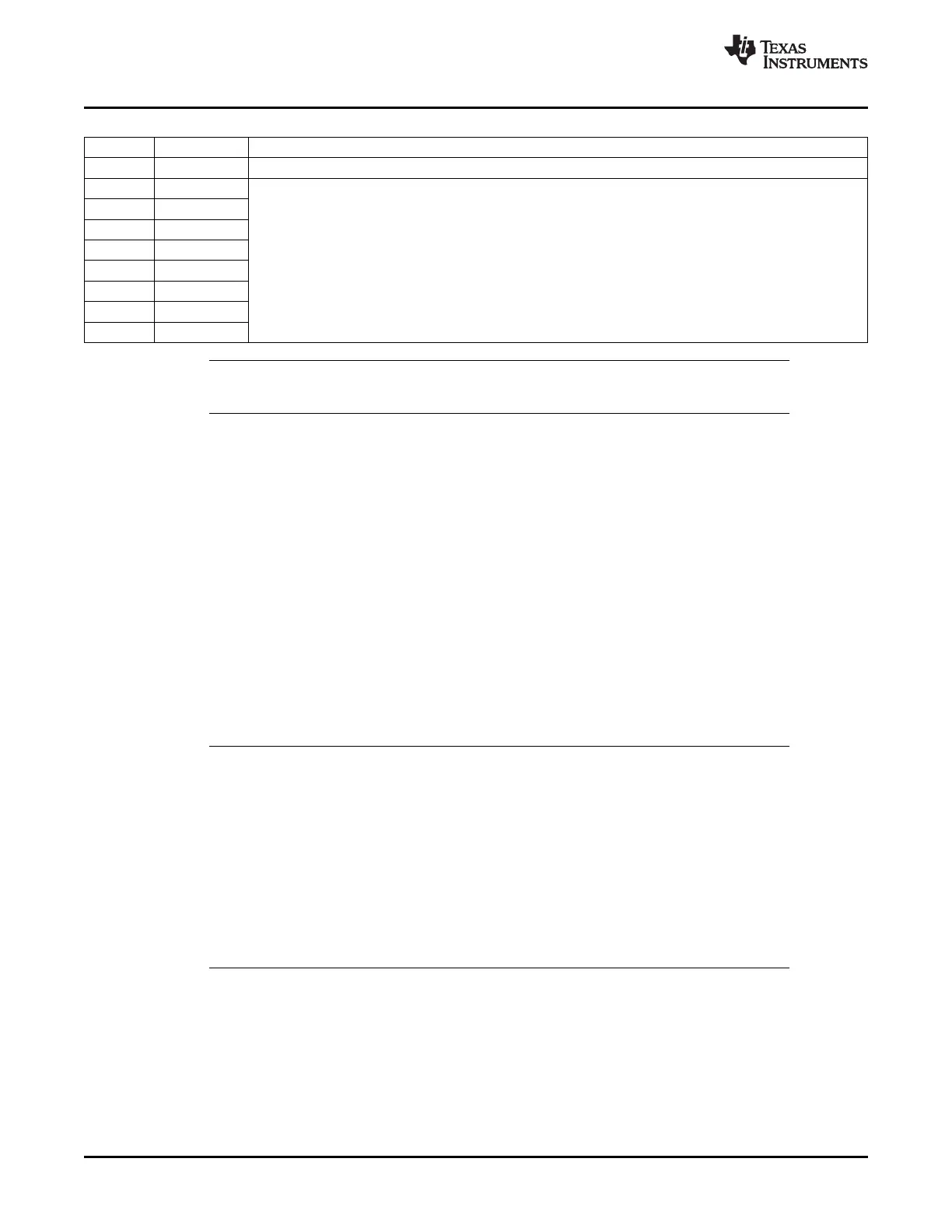
Table 6-10. PIEIERx Register (x = 1 to 12) Field Descriptions
Bits Field Description
15-8 Reserved Reserved
7 INTx.8 These register bits individually enable an interrupt within a group and behave very much like the core interrupt
enable register. Setting a bit to 1 enables the servicing of the respective interrupt. Setting a bit to 0 disables
6 INTx.7
the servicing of the interrupt. x = 1 to 12. INTx means CPU INT1 to INT12
5 INTx.6
4 INTx.5
3 INTx.4
2 INTx.3
1 INTx.2
0 INTx.1
Note: Care must be taken when clearing PIEIER bits during normal operation. See Section
Section 6.3.2 for the proper procedure for handling these bits.
The CPU interrupt flag register (IFR), is a 16-bit, CPU register and is used to identify and clear pending
interrupts. The IFR contains flag bits for all the maskable interrupts at the CPU level (INT1-INT14,
DLOGINT and RTOSINT). When the PIE is enabled, the PIE module multiplexes interrupt sources for
INT1-INT12.
When a maskable interrupt is requested, the flag bit in the corresponding peripheral control register is set
to 1. If the corresponding mask bit is also 1, the interrupt request is sent to the CPU, setting the
corresponding flag in the IFR. This indicates that the interrupt is pending or waiting for acknowledgment.
To identify pending interrupts, use the PUSH IFR instruction and then test the value on the stack. Use the
OR IFR instruction to set IFR bits and use the AND IFR instruction to manually clear pending interrupts.
All pending interrupts are cleared with the AND IFR #0 instruction or by a hardware reset.
The following events also clear an IFR flag:
• The CPU acknowledges the interrupt.
• The 28x device is reset.
Notes:
1. To clear a CPU IFR bit, you must write a zero to it, not a one.
2. When a maskable interrupt is acknowledged, only the IFR bit is cleared automatically.
The flag bit in the corresponding peripheral control register is not cleared. If an
application requires that the control register flag be cleared, the bit must be cleared by
software.
3. When an interrupt is requested by an INTR instruction and the corresponding IFR bit is
set, the CPU does not clear the bit automatically. If an application requires that the IFR
bit be cleared, the bit must be cleared by software.
4. IMR and IFR registers pertain to core-level interrupts. All peripherals have their own
interrupt mask and flag bits in their respective control/configuration registers. Note that
several peripheral interrupts are grouped under one core-level interrupt.
142 Peripheral Interrupt Expansion (PIE) SPRUFB0C – September 2007 – Revised May 2009
Submit Documentation Feedback
 Loading...