www.ti.com
Register Bit Definitions
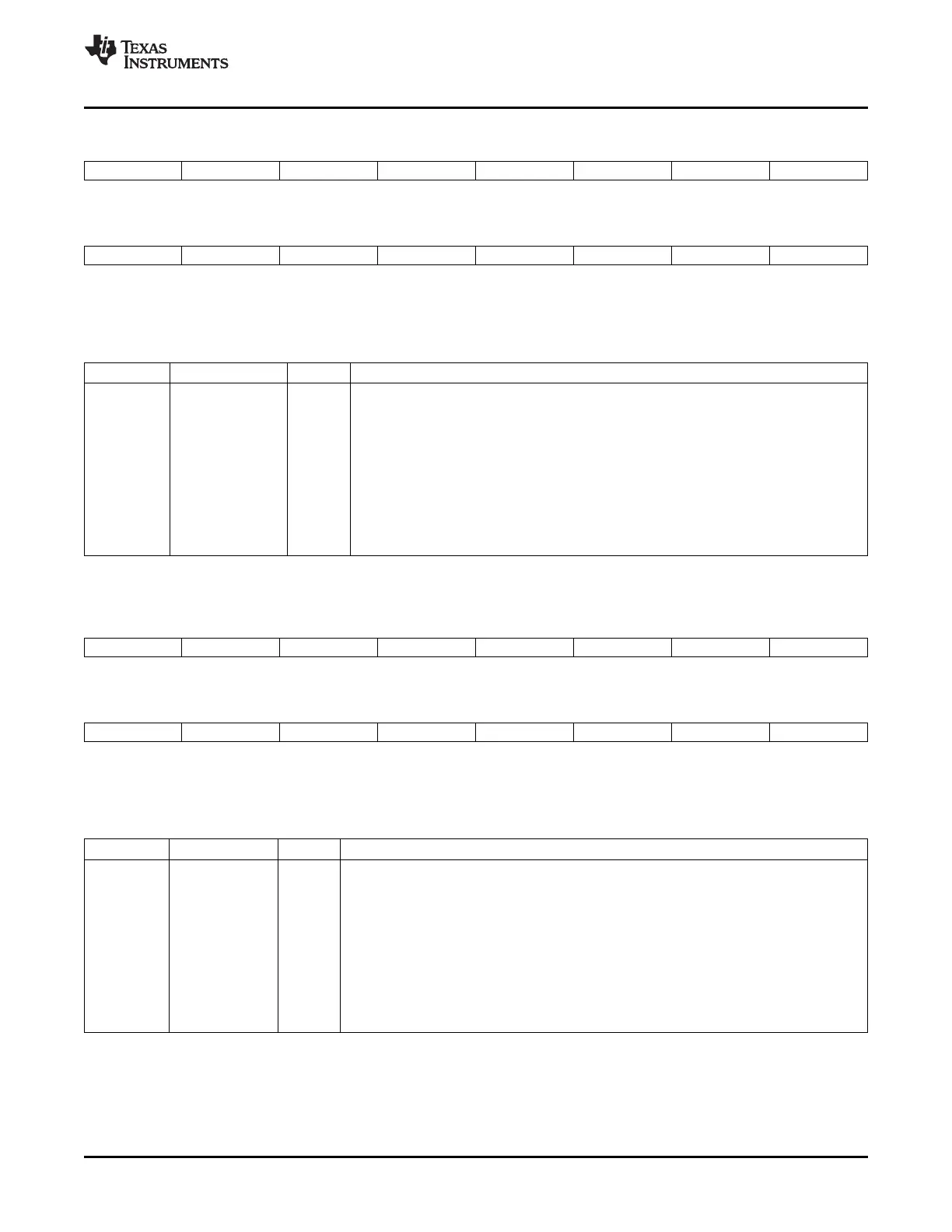
Figure 4-18. GPIO Port B Qualification Select 1 (GPBQSEL1) Register
31 30 29 28 27 26 25 24 23 22 21 20 19 18 17 16
GPIO47 GPIO46 GPIO45 GPIO44 GPIO43 GPIO42 GPIO41 GPIO40
R/W-0 R/W-0 R/W-0 R/W-0 R/W-0 R/W-0 R/W-0 R/W-0
15 14 13 12 11 10 9 8 7 6 5 4 3 2 1 0
GPIO39 GPIO38 GPIO37 GPIO36 GPIO35 GPIO34 GPIO33 GPIO32
R/W-0 R/W-0 R/W-0 R/W-0 R/W-0 R/W-0 R/W-0 R/W-0
LEGEND: R/W = Read/Write; R = Read only; - n = value after reset
Table 4-22. GPIO Port B Qualification Select 1 (GPBQSEL1) Register Field Descriptions
Bits Field Value Description
(1)
31-0 GPIO47-GPIO32 Select input qualification type for GPIO32 to GPIO47. The input qualification of each GPIO
input is controlled by two bits as shown in Figure 4-16 .
00 Synchronize to SYSCLKOUT only. Valid for both peripheral and GPIO pins.
01 Qualification using 3 samples. Valid for pins configured as GPIO or a peripheral function.
The time between samples is specified in the GPACTRL register.
10 Qualification using 6 samples. Valid for pins configured as GPIO or a peripheral function.
The time between samples is specified in the GPACTRL register.
11 Asynchronous. (no synchronization or qualification). This option applies to pins configured
as peripherals only. If the pin is configured as a GPIO input, then this option is the same as
0,0 or synchronize to SYSCLKOUT.
(1)
This register is EALLOW protected. See Section 5.2 for more information.
Figure 4-19. GPIO Port B Qualification Select 2 (GPBQSEL2) Register
31 30 29 28 27 26 25 24 23 22 21 20 19 18 17 16
GPIO63 GPIO62 GPIO61 GPIO60 GPIO59 GPIO58 GPIO57 GPIO56
R/W-0 R/W-0 R/W-0 R/W-0 R/W-0 R/W-0 R/W-0 R/W-0
15 14 13 12 11 10 9 8 7 6 5 4 3 2 1 0
GPIO55 GPIO54 GPIO53 GPIO52 GPIO51 GPIO50 GPIO49 GPIO48
R/W-0 R/W-0 R/W-0 R/W-0 R/W-0 R/W-0 R/W-0 R/W-0
LEGEND: R/W = Read/Write; R = Read only; - n = value after reset
Table 4-23. GPIO Port B Qualification Select 2 (GPBQSEL2) Register Field Descriptions
Bits Field Value Description
(1)
31-0 GPIO63-GPIO48 Select input qualification type for GPIO48 to GPIO63. The input qualification of each GPIO
input is controlled by two bits as shown in Figure 4-17 .
00 Synchronize to SYSCLKOUT only. Valid for both peripheral and GPIO pins.
01 Qualification using 3 samples. Valid for pins configured as GPIO or a peripheral function. The
time between samples is specified in the GPACTRL register.
10 Qualification using 6 samples. Valid for pins configured as GPIO or a peripheral function. The
time between samples is specified in the GPACTRL register.
11 Asynchronous. (no synchronization or qualification). This option applies to pins configured as
peripherals only. If the pin is configured as a GPIO input, then this option is the same as 0,0
or synchronize to SYSCLKOUT.
(1)
This register is EALLOW protected. See Section 5.2 for more information.
SPRUFB0C – September 2007 – Revised May 2009 General-Purpose Input/Output (GPIO) 97
Submit Documentation Feedback
 Loading...