Chapter 6
59
UM10350_PCNC770_Manual_0916A
PathPilot Interface
Whether using the jog shule or the keyboard arrow keys, there are two modes of jogging,
connuous and step. When using the keyboard to jog, switch between modes using the Jog Cont/
Step buon (see Figure 6.7).
Step Mode – In Step mode the mill jogs in steps, where the step size is controlled by the four buons
to the right of the Step label (see Figure 6.7).
Connuous Mode – In Connuous mode the mill jogs at a connuous velocity when you press and
hold any one keyboard arrow key; stop the mill by releasing the key. Axis moon is key specic as
shown in Figure 6.6. The velocity is set using the Jog Speed Slider (see Figure 6.7). To set jogging
velocity to the maximum speed, click and drag the Jog Speed Slider to the far right posion.
Feed Rate DRO – Feed rate is the velocity at which the workpiece can be fed against the machine
tool. The DRO, or digital read out, is the eld that displays this velocity.
Noce that in imperial units (type G20 in the MDI Line) the step sizes range from 0.0001” to 0.1”
(see Figure 6.7), whereas in metric mode (type G21 in the MDI Line) the step sizes range from .01
mm to 10 mm. The illuminated LED in the upper right corner of each Step buon indicates acve
step size.
Spindle Controls – The REV, Stop, and FWD buons can be used to manually control the spindle
(see Figure 6.8). Rev is the equivalent of typing M04 in the MDI Line – it starts the spindle counter
clockwise at the RPM specied in the Spindle RPM DRO (see Figure 6.8).
The Stop buon stops the spindle, similar to the M5 command. The FWD buon starts the spindle
clockwise at the set RPM. These buons are unavailable when running a G-code program or in the
middle of an MDI move. Pressing REV or FWD triggers an alarm if the commanded spindle speed is
outside of the valid spindle speed range for the mill's current belt posion.
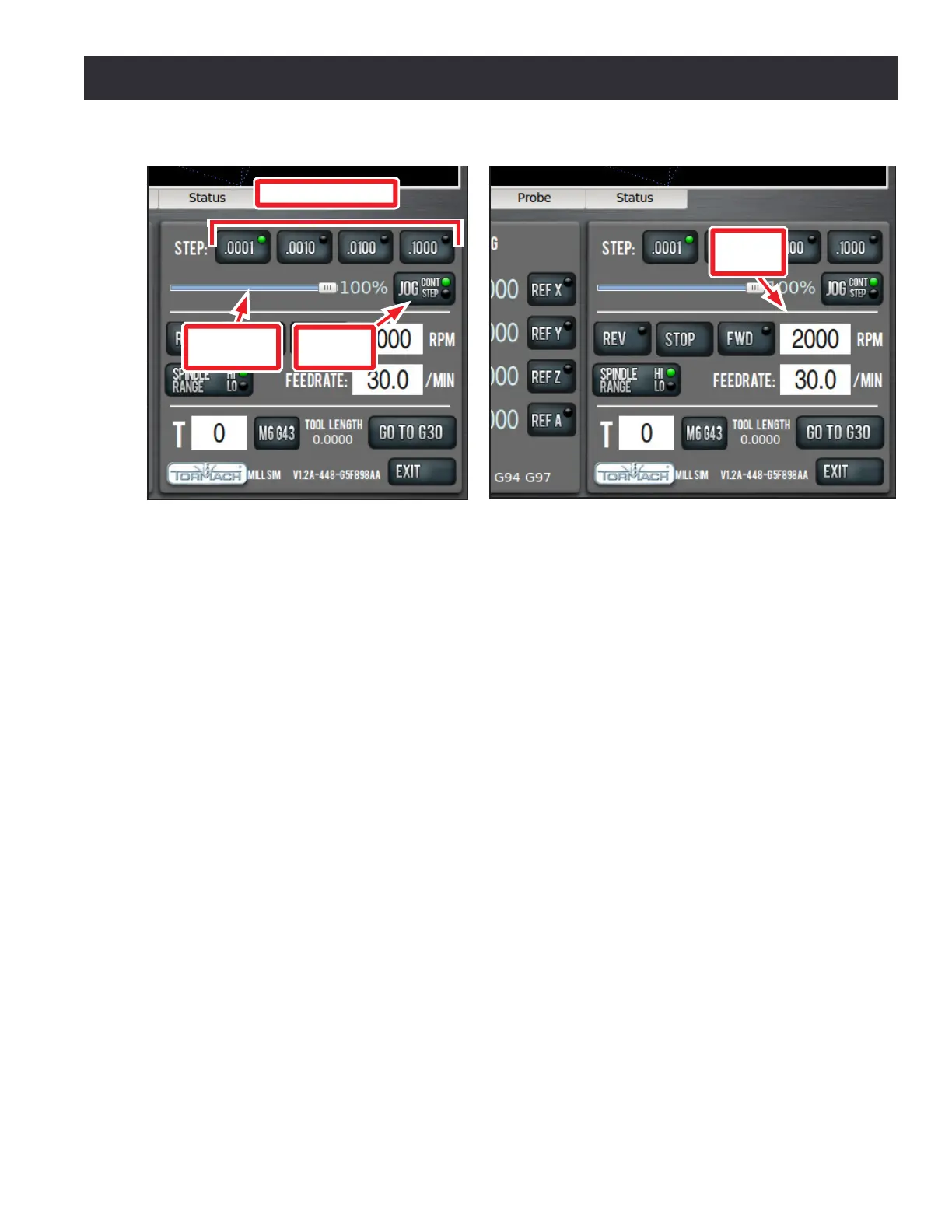
Figure 6.7
Jog Cont/
Step
Jog Speed
Slider
Step Size Buttons
Figure 6.8
Spindle
RPM