Chapter 6
63
UM10350_PCNC770_Manual_0916A
PathPilot Interface
When used in conjuncon with the FIND
command, certain search terms (listed below)
iniate a search through the G-code le to nd
more than just the actual search term:
• FIND TOOL: Searches for instances of the
actual word Tool in the G-code and any T
G-code command, which calls up a tool
(e.g., T12)
• FIND SPEED: Searches for instances of the
actual word Speed in the G-code and any S
G-code command
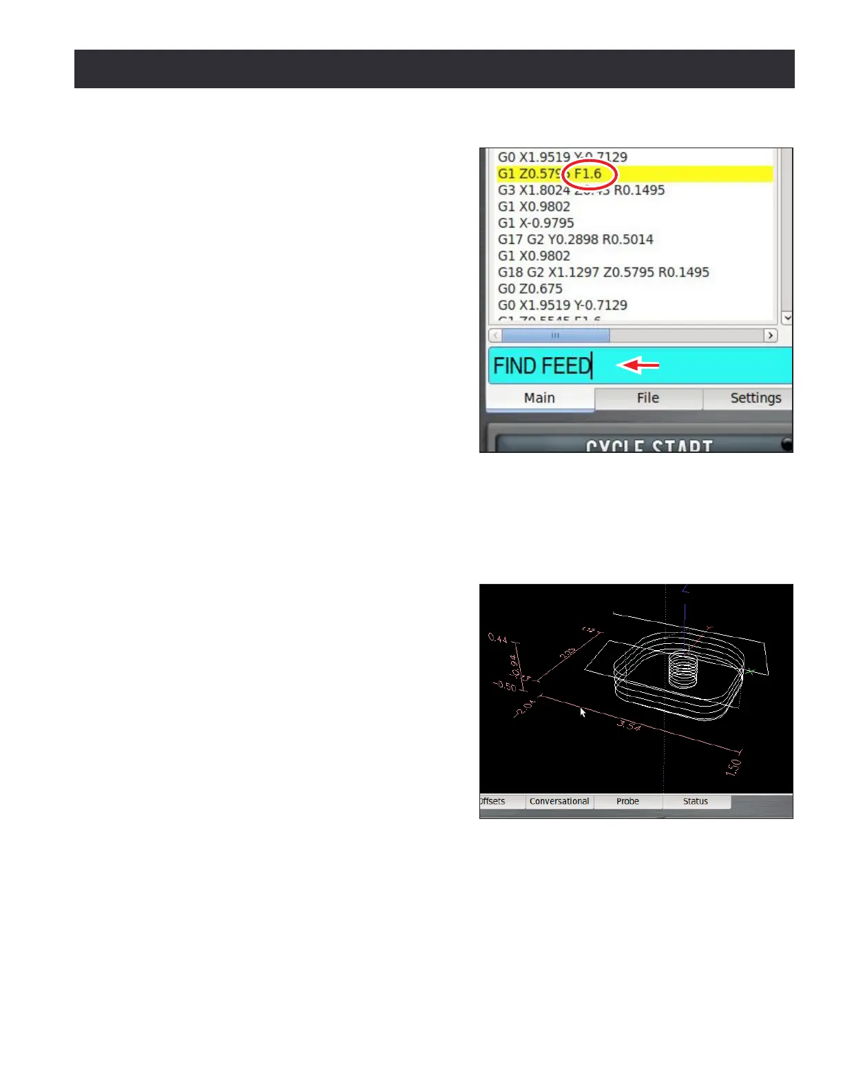
• FIND FEED: Searches for instances of the
actual word Feed in the G-code and any F
G-code command (see Figure 6.12)
NOTE: Search text ignores case, so the command FIND
TOOL will match TOOL, Tool, tool, etc.
The FIND command simplies searching of a G-code le to verify speed and feed values and tool
calls before cung a part, or to nd a specic set start line point in a large G-code le. For more
informaon on using set start line, refer to G-code Window earlier in this secon.
Tool Path Display – The tool path window displays
a graphic representaon of the tool path that is
executed for the currently loaded G-code le (see
Figure 6.13). Preview lines are shown in white,
the tool path as it is cut is red, and jogging moves
are yellow. The boundary box, drawn in doed
blue, represents the ends of travel of the axes.
Erase the yellow jogging and red tool path lines at
any me by double-clicking the display or clicking
the Reset buon.
Four views are available: top, front, right, and
ortho. The default view aer loading a new
G-code program is top. To switch between views,
right click anywhere in the tool path display and
choose the desired view.
Grid lines are visible behind the tool path when the view is top, front, or side (not ortho). By default,
these are drawn at 0.5” intervals (5 mm intervals when in G21 mode). To change the resoluon of
the grid lines, right click anywhere in the tool path display to select the desired grid spacing. Noce
that when a program is loaded, the program extents (furthest points to which the tool will travel
while execung the G-code) are displayed to the le and boom of the tool path (see Figure 6.13).
Figure 6.12
Figure 6.13