OPTIONS & ALLIED TOOLING − DECO 7/10 − DECO 7a/10a − DECO 7e/10e
300236 en − 02/07 Chap. 7.1 /2
Standard equipment
− 1 adjusting dolly
− 2 cutter holder dollies:
− 1 set of wrenches
Note:
To guarantee optimum precision, the dollies are paired with the equip-
ment. To order dollies please indicate the equipment no.
This no. is on the geometry inspection sheet of the machine folder.
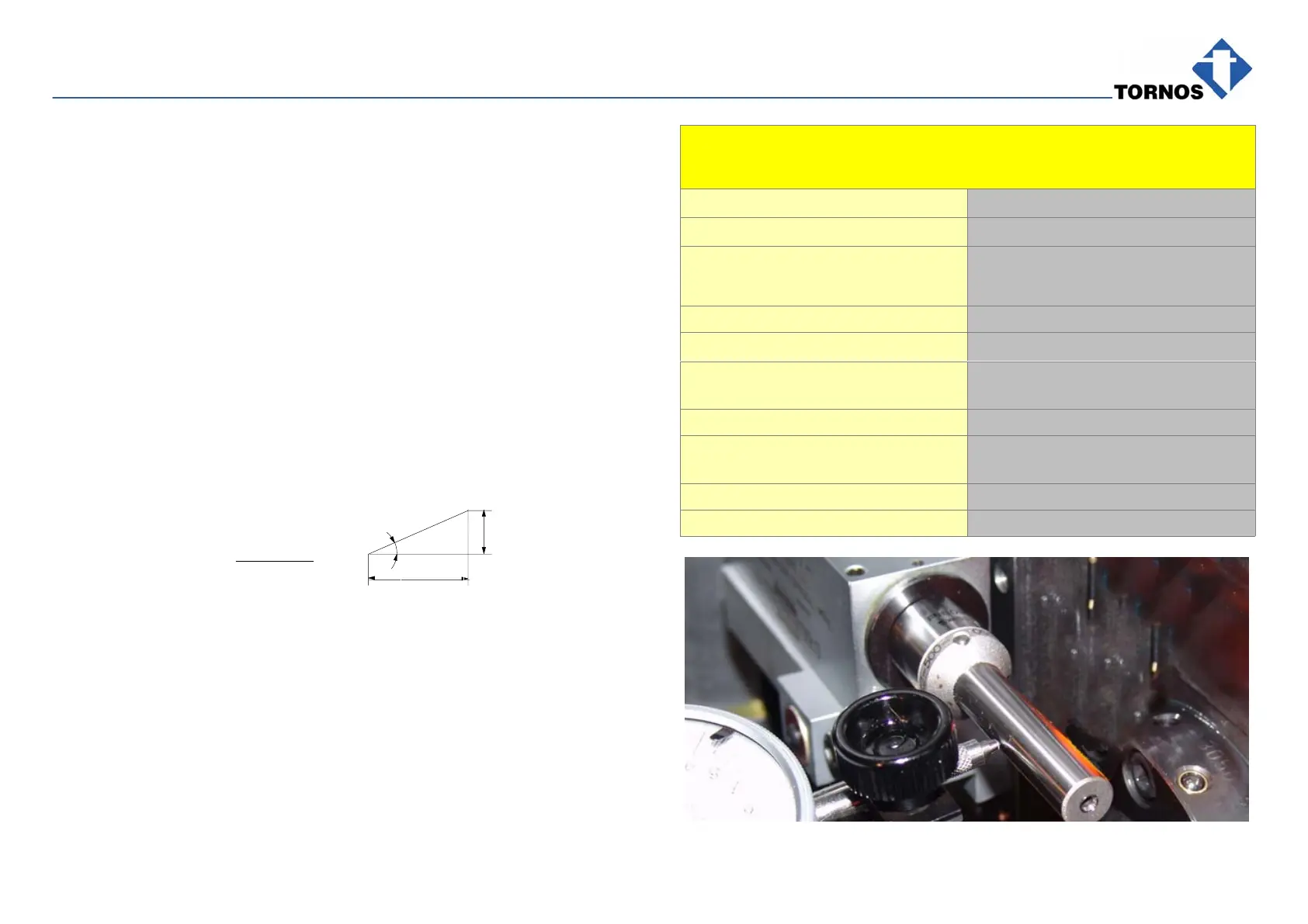
7.1 INCLINATION OF THE EQUIPMENT
The angle is indicated on the cutter. If that is not the case, use the following
formula:
For example: pitch t = 0.36 / angle = 32’ / Dp = ∅ cut pitch−line
t
Dp x π
tg α =
α
Dp x π
t
ADJUSTING THE DEVICE INCLINATION
Starting condition: Pickoff spindle in upper position
Operations Notes
Assembly
Put the equipment in position...
Screw and lock the two 5 screws
fit by two pins.
see drive S2 (instr. 300651)
Install the adjusting dolly Lock with the screw 3.
Adjusting the angle
Install a comparator on chaser 1 or on
the spindle housing
Loosen the 2 screws 2.
Make a 10mm stroke in X with the
sensor.
With the angle 32’ you obtain a tg
of 0.09mm
Use screw 1
Lock the 2 screws 2.