OPTIONS & ALLIED TOOLING − DECO 7/10 − DECO 7a/10a − DECO 7e/10e
300236 en − 02/07 Chap. 10.5.3 /8
10.5 SENSOR CONTROL OPERATION (AN EXAMPLE)
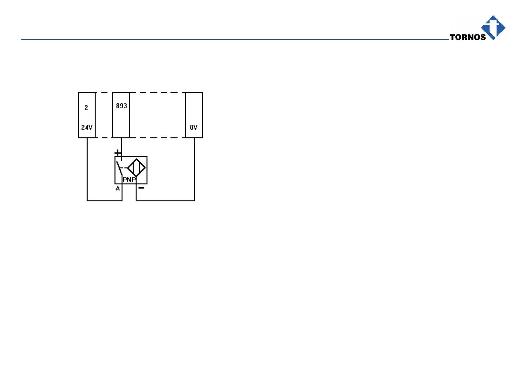
10.5.1Wiring Diagram for Optional Socket 2
Terminal box
XT 800
40
When Input 1 of the optional socket goes over to 1 (24V), the program stops
at the end of table (Alarm Class 1)
10.5.2Configurating Optional Socket 2 Outside Program Loop
M800 P1=1773 P2=1776:
1773 disables unused Input 2.
1776 selects Alarm Class 1.
10.5.3Enable Check by Input 1 Inside Program Loop
M825: enables check start,
generates 100 ms impulse to enable checking Input 1 on Socket 2.
If Input 1 on Socket 2 is at 1 and M825 enabled, Alarm 2012: ALARM CLASS
1 OPTION SOCKET is displayed and the program stops at the end of table.