OPTIONS & ALLIED TOOLING − DECO 7/10 − DECO 7a/10a − DECO 7e/10e
300236 en − 02/07 Chap. 16.4.3 /14
Geometrics
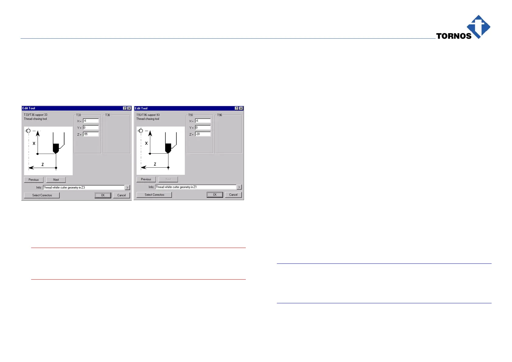
For correct whirling program, you need Tool T33 with Support 33 as well as
Tool T93 with Support 93.
Geometrical settings are as follows :
T93 geometry is important: It determines the distance for the whirling attach-
ment in relation to the guidebush. Setting −20 precludes any crash between
the whirling spindle and the guidebush.
. Caution !
Already with −19, the whirling attachment is sensitively closer to the
guidebush and you must be very careful while running the program !
T33 geometry in Z3 is −55 and must never be altered. This is the geometry
of the cutters, measured from Machine Zero (see Fig. 305115e).
Thread Length Correction
A wrong thread length requires entering a correction only in OFFSET of T93
geometry in Z1. This must be done on the machine.
16.4.3 Technical Data and Calculations for External Whirling
Working diameter of cutters (geometry) :
6 mm
Cutting speed :
94 m/min
n = Attachment Speed :
5000 rpm
fz = Feed per Tooth :
0.025 mm
z = No. Teeth :
3
Note :
Feed per Tooth fz is gained from experience with whirling. Usually it is
within 0.02 to 0.05 mm. The feed can be optimized to obtain good qual-
ity of thread and good control of cutter wear.
 Loading...