OPTIONS & ALLIED TOOLING − DECO 7/10 − DECO 7a/10a − DECO 7e/10e
300236 en − 02/07 Chap. 10.6.3 /9
10.6 DRILL SENSOR CONTROL (AN EXAMPLE)
Drill sensor activated by pneumatic piston.
Sensor signal is wired to Input 1 on Optional Socket 1.
Pneumatic valve is wired to Output 1 on Optional Socket 1.
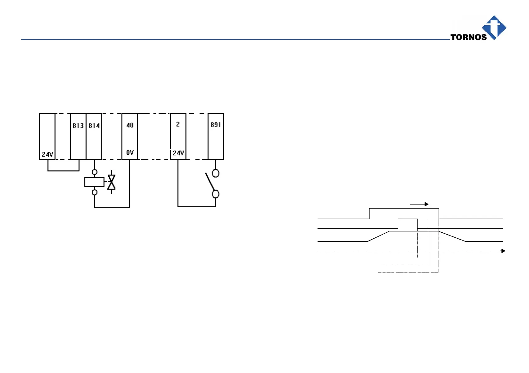
WIRING DIAGRAM FOR OPTIONAL SOCKET 1
Terminal
Box
XT 800
2
10.6.1Configurating Optional Socket 1 Outside Program Loop
In tool absence: the program stops at the end of table (Alarm Class 1).
M800 P1=1750 P2=1753 P3=1756: 1750 reverses Input 1.
1753 disables unused Input 2.
1756 selects Alarm Class 1.
In tool presence: the program stops instantaneously (Alarm Class 3).
M800 P1=1753 P2=1757: 1753 disables unused Input 2.
1757 selects Alarm Class 3.
10.6.2Enable Check Inside Program Loop
M815: enables check start.
M811 D811=300: Sensing command response time: 300 ms
M812: disables sensing command.
In tool absence
(input is 0 and M815 enabled): Alarm 2012: ALARM CLASS 1
OPTION SOCKET is displayed and the program stops at the end of table.
In tool presence
(input is 1 and M815 enabled): Alarm 1013: ALARM CLASS 3
OPTION SOCKET is displayed and the program stops at the end of table.
10.6.3Timing Diagram for Drill Check Sensor
Input 1
on Socket 1
M815
Sensor motion
Time [ITP]
M815
M811
M812
300 ms
100 ms