OPTIONS & ALLIED TOOLING − DECO 7/10 − DECO 7a/10a − DECO 7e/10e
300236 en − 02/07 Chap. 16.3.2 /7
16.3.2 Axial Alignment of Cutters
To start with : Remove the centering arbor and fit Spindle
No. 217213 + Cutter Head No. 570952.
Align cutters axially to adhere to the 132 mm
dimension in Fig. 305115d.
What to do ? Notes
Example in Fig. 1505 :
(see following page)
To fit the spindle :
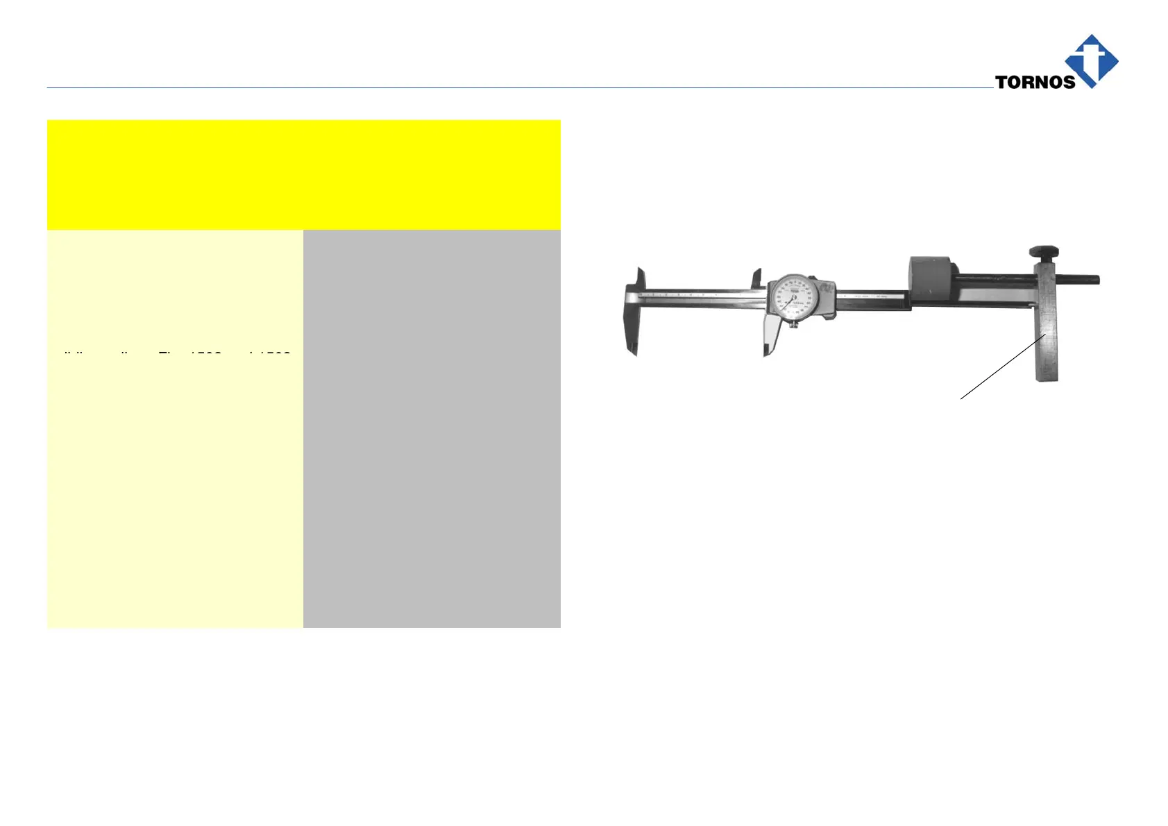
Place Rule 1 at 93 mm with the
sliding caliper, Fig. 1502 and 1503.
with cutter profile centered 2 mm
off cutters base.
Place Rule 1 at 93 mm with the
sliding caliper, Fig. 1502 and 1503
Position the spindle at 93 mm by
locating Magnetic Shoe 2 on the
base and pushing cutters base
against Rule 1.
Rule 1 is delivered with the attach-
ment.
Example in Fig. 1506 :
(see following page)
Retract the spindle by 1 mm.
To fit the spindle :
Proceed as in the first example
above above but place Rule 1 at
92 mm (93 − 1 = 92 mm).
with cutter profile centered 3 mm
off cutters base.
. Caution !
Cutter profile center must be
always at 132 mm.
1502
Length gauge