OPTIONS & ALLIED TOOLING − DECO 7/10 − DECO 7a/10a − DECO 7e/10e
300236 en − 02/07 Chap. 10.11 /16
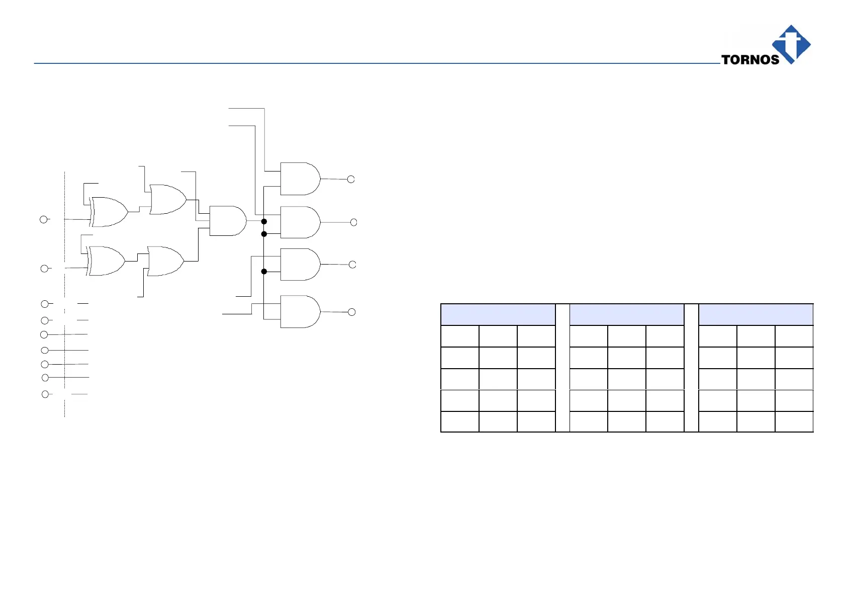
10.10OPTIONAL SOCKET DIAGRAM WITH DO ALLOCATION
1
2
5
6
7
8
9
In1
In2
Flag 2
Flag 1
Flag 3
Flag 5
Flag 6
Flag 7
Flag 8
Flag 9
Class 0
Class 1
Class 3
Event 7
Out 1
Out 2
24 V= (2x)
0V (2x)
Gnd
4
3
Flag 4
Flags 1 and 2: reverse Inputs In1 and In2.
Flags 3 and 4: disable Inputs In1 and/or In2.
Flag indication 1 disables the input.
Flag 5: determines when check starts (ck).
Flags 6 to 8: determine actions to be enabled.
Gates 6, 7, 8, 9 are actually flip-flops to be reinitialized by PMC
when program starts.
Flag 9: enables Register Event 7.
(cf. the concept of sequences)
10.11 RECAP OF LOGICAL FUNCTIONS
XOR (Gates 1 and 2) OR (Gates 3 and 4) AND (Gates 5 to 9)
A B OUT A B OUT A B OUT
0 0 0 0 0 0 0 0 0
0 1 1 0 1 1 0 1 0
1 0 1 1 0 1 1 0 0
1 1 0 1 1 1 1 1 1