OPTIONS & ALLIED TOOLING − DECO 7/10 − DECO 7a/10a − DECO 7e/10e
300236 en − 02/07 Chap. 7.2 /3
7.2 PRESETTING
GEOMETRY ON THE PRE−SETTER
Operations Notes
Steps to take
Create a mark on the cutter so you
always take the geometry on the
same tooth.
Mount the cutter−holder dolly
Install the equipment on base 10a
and check the roundness. (max 2μ)
Δ Attention! The dollies need to
be clean and free from burrs.
Change the dolly if the tolerance
is not in conformity.
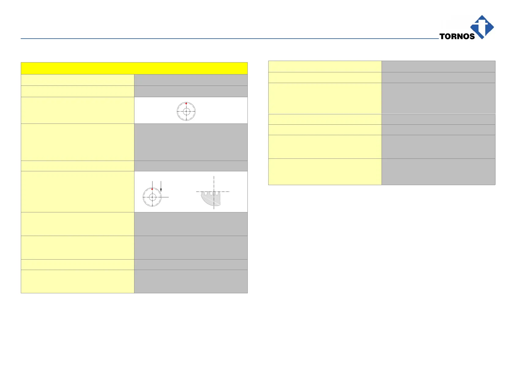
Geometry in X Following the example (pitch = t)
Position in the middle of the first
complete tooth.
Value read: 1.08mm
Y
Z
1/4 t
1/4 t
X
Work: cutter under the part: subtract 1/4 pitch
1,08 − 0,09 = 0,99
Work: cutter on the part: add 1/4 pitch
1,08 + 0,09 = 1,17
Geometry in Z
Value read: −12.98mm
Subtract cutter radius (negative):
−12,98 + −6 = −18,98
Operations Notes
Geometry in Y
Fixing in pos: T22, T23 and T24
Offset of 28.5mm between the pin
and equipment cutter axis
Work:
cutter under and on the part
Work: cutter on the part: −28,5 + −6 = −34,5
Work: cutter under the part: −28,5 − −6 = −22,5
Fixing in pos: T25
Programming and work in T24
Δ Attention! Work: only under the
part.
Offset + cutter radius + fixing pin
centre−to−centre distance on
chaser
−28,5 + −6 + 30 = −4,5