TestProcedure(continued)
3.ReadallWarning,Cautions,andprecautionslistedatthebeginningofthis
section.
4.Raiseandsupporttheoperatorseat,removetheseatplatetogetaccessto
thehydraulicpumpassembly.
5.EnsurethatthetractionpedalisintheNEUTRALposition,thesteeringwheel
isstationaryandparkingbrakeisset.
g226949
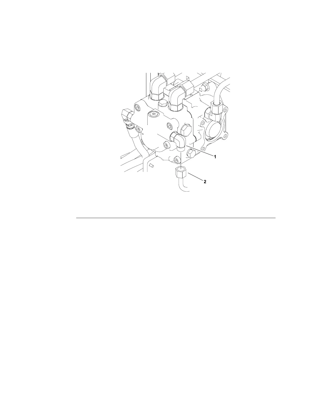
Figure68
1.90°hydraulictting
2.Hydraulictube
6.Cleanthettingandhydraulictube(Figure68).Loosenandremovethetube
fromthetting.Installateettingwitha35,000kPa(5,000psi)pressure
gaugebetweenthettinganddisconnectedtube.
7.Attachaheavychaintotherearofthemachineframeandanimmovable
objecttopreventthemachinefrommovingduringtesting.
8.Blockthewheelswithchockstopreventthewheelrotationduringtesting.
9.Starttheengineandmovethethrottletofullspeed(3,100to3,250rpm)
position.Useatachometertocheckthattheenginespeediscorrect.
10.Recordthereadingonthechargecircuitpressuregauge.Thecharge
pressure(withoutload)shouldread345to483kPa(50to70psi).Ifthe
chargereliefpressurespecicationisnotmet,considerthefollowing:
A.Thehydraulicpumpchargereliefvalveisdamaged.Repairorreplace
thehydraulicpumpchargereliefvalve;refertoServicingtheHydraulic
Pump(MachineSerialNumberabove316000000)(page5–103).
11.Sitintheoperator’sseat,releasetheparkingbrake,andslowlypressthe
tractionpedalforwarduntil8,963to13,100kPa(1,300to1,900psi)is
reachedonthetractioncircuitpressuregauge.
HydraulicSystem:TestingtheHydraulicSystem
Page5–60
Groundsmaster
®
3280-D/3320
05138SLRevB
 Loading...


