DisassemblytheLiftControlValve(continued)
5.CarefullyremoveO-rings(item4inFigure104)fromspoolbore.Takecare
nottodamagespoolboreorO-ringcavitiesduringO-ringremoval.
6.Removedetentplug(item16inFigure104),O-ring,spring,anddetentball.
7.Removeplug(item9inFigure104)withO-ring,andlockoutseatwithO-ring
fromvalvebody.
8.Removeadapterplug(item14inFigure104)withO-ring,poppetstop,
spring,andpoppetfromcontrolvalvebody.
9.Removelockoutseat(item22inFigure104)withO-ringfromcontrolvalve
body.Removedetentplunger.
g230844
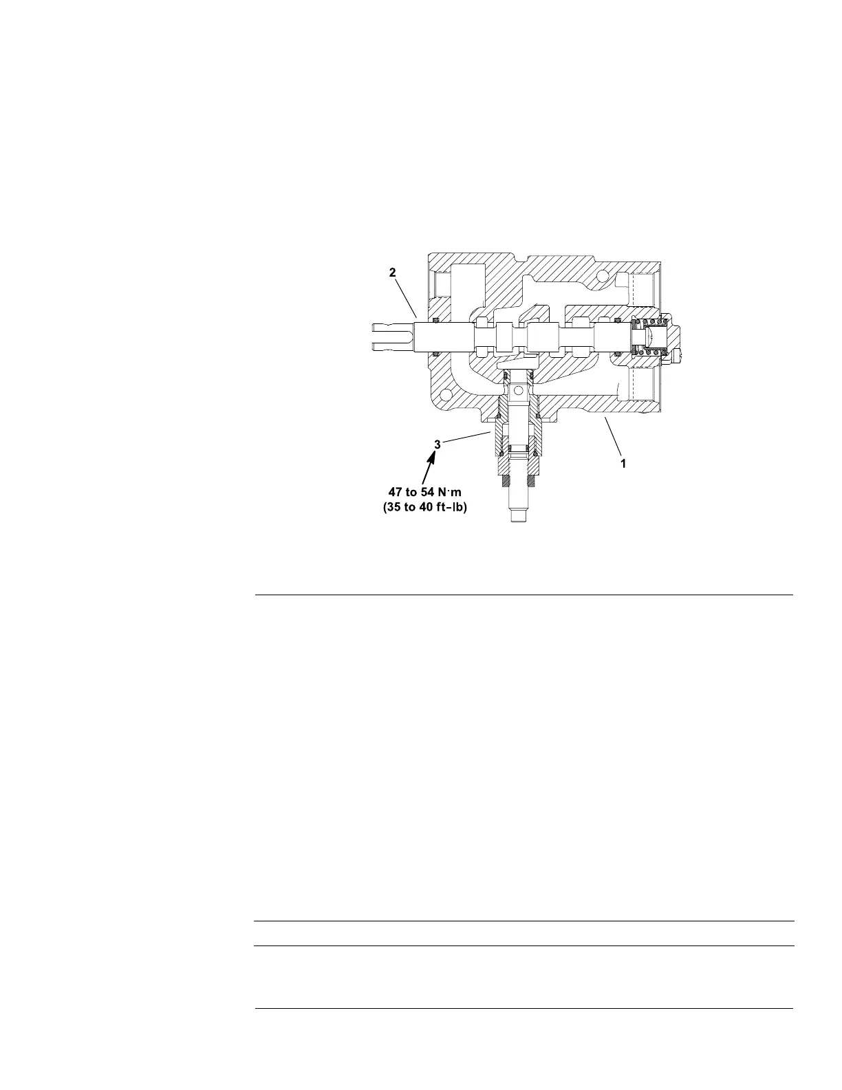
Figure105
1.Liftcontrolvalve2.Spool3.Counterbalancevalve
10.Ifcontrolvalveisequippedwithcounterbalancevalve(Figure105),remove
valvefromcontrolvalveifnecessary.Counterbalancevalvedisassembly
isnotrecommended.
InspectingtheLiftControlValve
1.Inspectspoolandspoolboreforwear.Ifwearisexcessive,replacelift
controlvalveassembly.
2.Inspectallspringsandreplaceifdamagedorbroken.
3.Inspectdetentplunger,detentball,andpoppetforwear.Replaceas
necessary.
4.Inspectlockoutseatsforwearordamage.Replaceasnecessary.
5.InspectcontrolvalvehousingthreadsandO-ringsealingsurfaces.Replace
asnecessary.
6.InspectthreadsandO-ringsealingsurfacesonplugs.Replaceasnecessary.
AssemblingtheLiftControlValve
IMPORTANT
Donotwipepartswithdrypapertowelsorrags.Lintmaycause
damagetothehydraulicsystem.
Groundsmaster
®
3280-D/3320
Page5–131
HydraulicSystem:ServiceandRepairs
05138SLRevB
 Loading...


