InstallingtheInputShaft/PinionGear(4-WheelDriveAxle)(continued)
9.Useadepthgaugetomeasurethedistancefromtheendfaceoftheinput
shaft/piniongeartothematingsurfaceofthebearingcase.Subtractthe
designconecenterdistancefromthisdistancetodetermineinitialshim
thickness(Figure273).
Designconecenterdistance(distancefrommatingsurfaceoftheaxle
supporttotheendfaceofthepiniongear):47.50±0.05mm(1.870±0.002
inch)
Note:Bearingcaseshimsareavailablein0.10mm(0.004inch)and0.20
mm(0.008inch)thickness.
10.CoatanewO-ringwithgrease.Placeshimsonthebearingcaseand
temporarilyinstalltheinputshaft/piniongearassemblyintotheaxlecase.
Tightenthemountingscrewsto47to56N·m(35to41ft-lb).
g226492
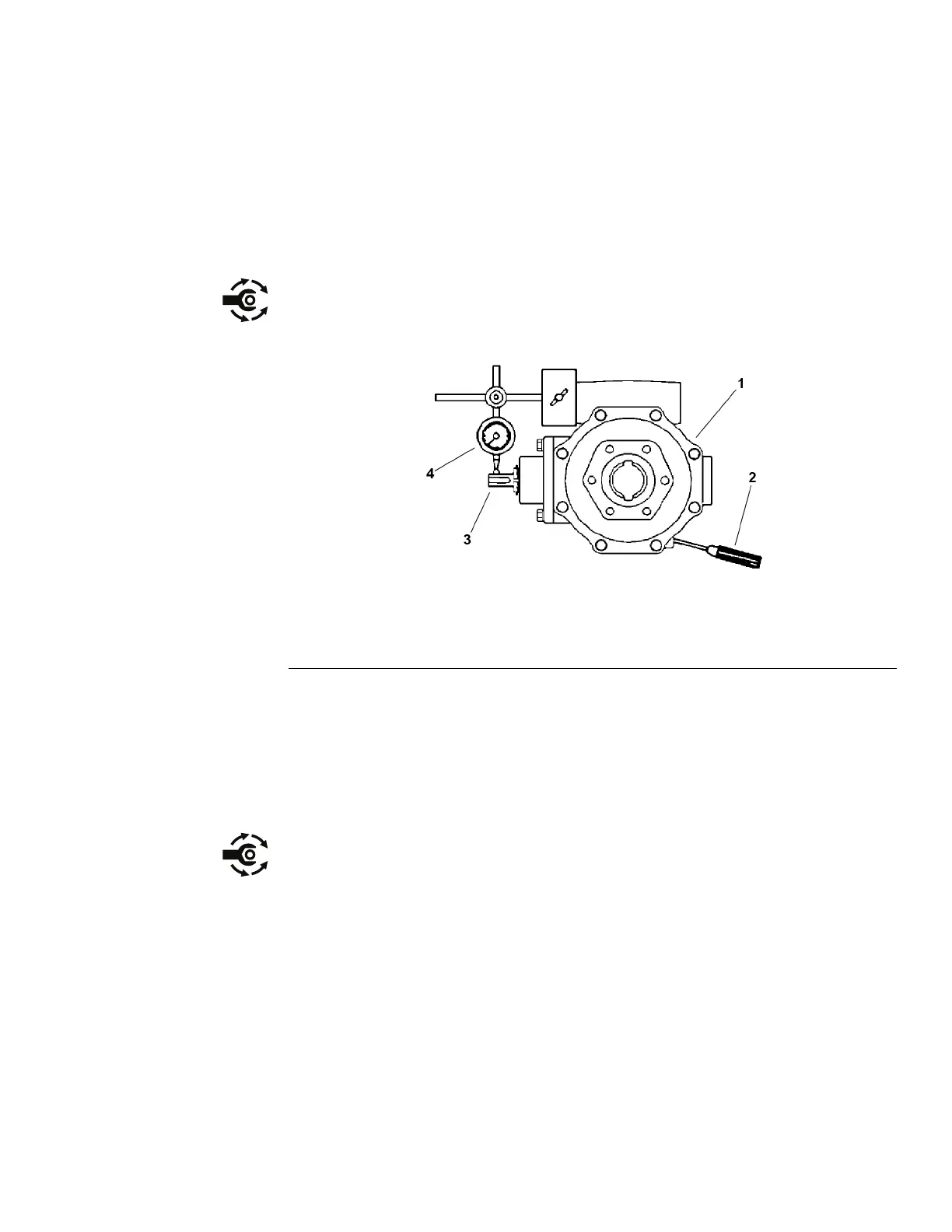
Figure274
1.Axlecase
3.Inputshaft/piniongear
2.Screwdriver
4.Dialindicator
11.Insertascrewdriverthroughthedrainplugholetoholdtheringgearand
measurethepiniongeartoringgearbacklash(Figure274).
Piniongeartoringgearbacklash:0.10to0.40mm(0.004to0.016inch)
12.Adjustbacklashbyincreasingorreducingthebearingcaseshimthickness.
13.Checkthepiniongeartoringgearengagement;refertoPinionGeartoRing
GearEngagement(4-WheelDriveAxle)(page8–70).
14.Placethecorrectcombinationofshimsonthebearingcase.Tightenthe
mountingscrewsto47to56N·m(35to41ft-lb).
Groundsmaster
®
3280-D/3320
Page8–63
DriveAxles:ServiceandRepairs
05138SLRevB
 Loading...


