RemovingtheBladeSpindle(continued)
4.Removethe8ribbedneckboltsand8angenutsthatsecurethespindle
assemblytothedeck,andremovethespindleassemblyfromthedeck.
InstallingtheBladeSpindle
g223662
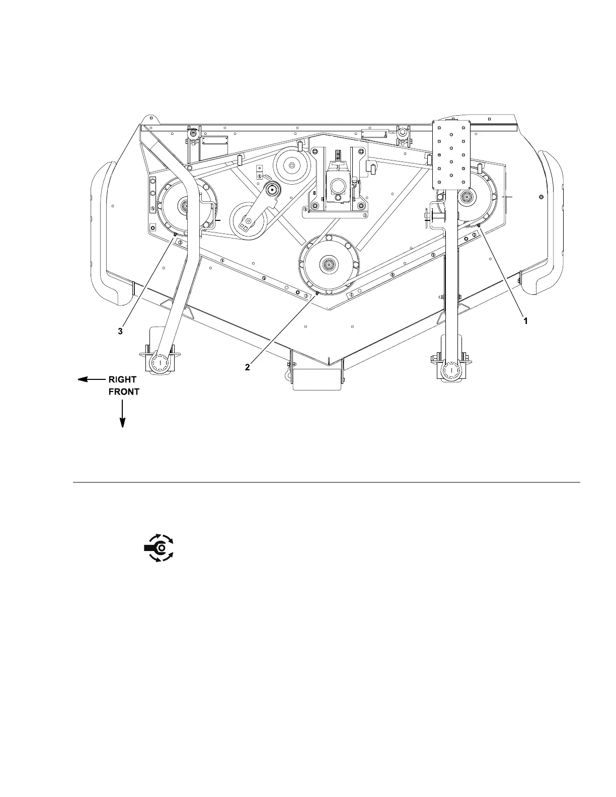
Figure297
1.Leftspindlegreasetting2.Centerspindlegreasetting3.Rightspindlegreasetting
1.Positionthespindleonthecuttingdeckandnotetheorientationofthegrease
tting(Figure297).Securethespindleassemblytothedeckwiththe8
ribbedneckboltsand8angenuts.
2.Installthecuttingblade,anti-scalpcup,andbladebolt;refertotheCutting
UnitOperator’sManual.T orquethebladeboltto115to149N∙m(85to
110ft-lb).
3.Slowlyrotatethecuttingbladestocheckthatthebladesdonotcontactany
deckcomponent(s).
4.Installthedrivebelttothedeckpulleys;refertotheCuttingUnitOperator’s
Manual.
5.Lubricatethespindlegreasettings.
6.Installthebeltcoverstothecuttingdeck;refertotheCuttingUnitOperator’s
Manual.
Groundsmaster
®
3280-D/3320
Page10–9
CuttingUnits:ServiceandRepairs
05138SLRevB
 Loading...


