C-3
Appendix C
System Technical Specifications
This chapter provides reference information for the IT2200 Reader
System with Multimode Capability components.
Component Specifications
This appendix describes the engineering specifications for the IT2200 Reader System
components.
IT2020 Reader Logic Card
Electrical Specifications
The reader logic card requires +5 VDC and +12 VDC power, which is supplied by the
host computer or lane controller power supply.
Circuit breakers and disconnects are unnecessary with the reader logic card. Because
all input and output signals have limited short circuit current drive, there is no need to
include a circuit breaker. Lightning protection is achieved through the use of optically
coupled signals between the reader logic card and the RF module. These two units are
connected via copper wire with optical isolation on the reader logic card. The card
provides all of the following interfaces: card edge, ISA, RS-232, optically isolated
input/output interface, optional external power, background debugger mode (BDM),
TDM, diagnostics, and IP daughterboard.
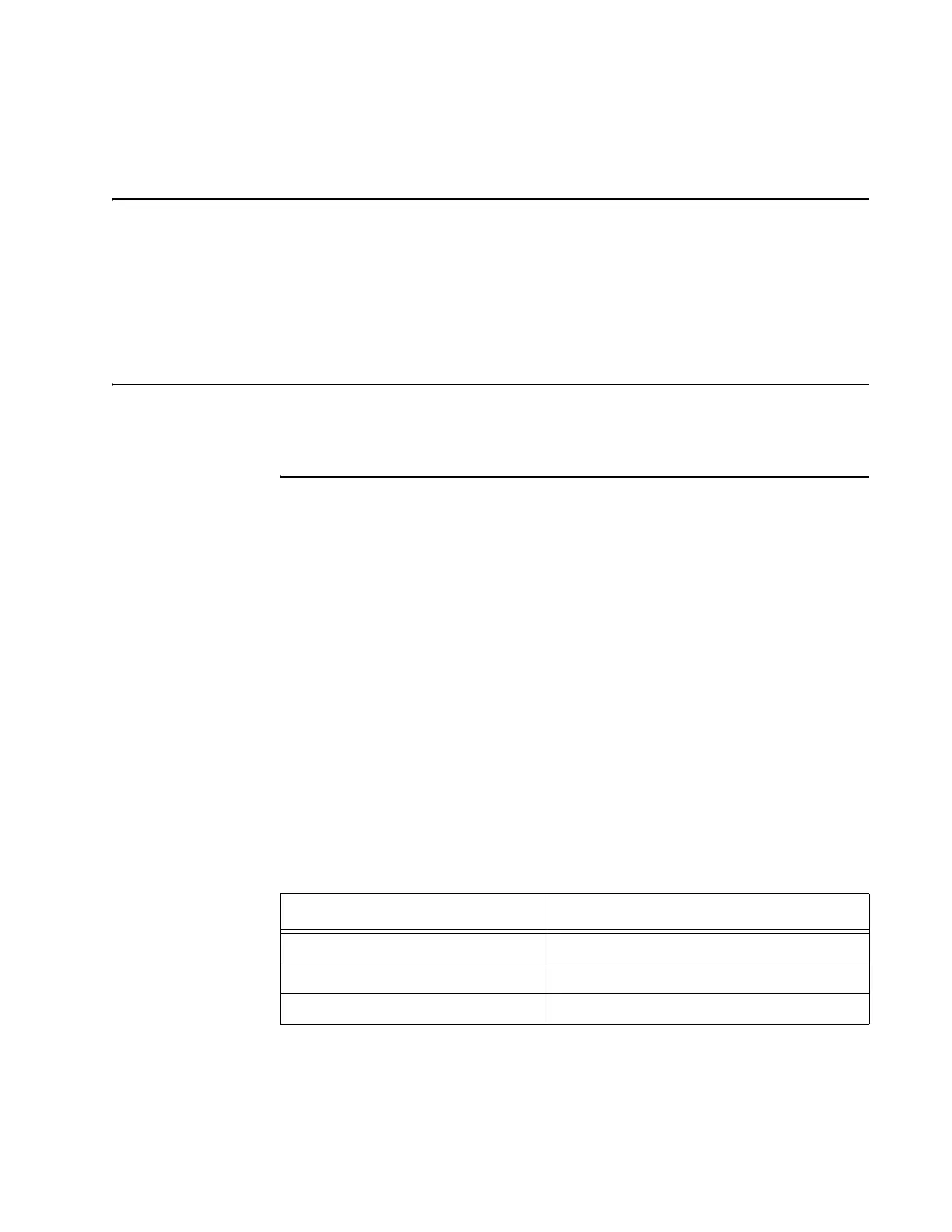
Table C-1 shows the electrical requirements for the IT2020 Reader Logic Card.
Table C-2 shows the power consumption estimates for the card’s individual assem-
blies.
Table C-1 IT2020 Reader Logic Card Electrical Requirements
Specification Value
Input power <10W
Power connections ISA bus or direct
Warm-up time < 30 seconds